Page 21
On-Board Links
Note: In icomfort systems with a conventional outdoor unit
(non-communicating), the on-board clippable links must
be set to properly confi gure the system.
WARNING
Carefully review all confi guration information provided.
Failure to properly set DIP switches, jumpers and on-
board links can result in improper operation!
On-Board Link W914 Dehum or Harmony (R to DS)
On-board link W914, is a clippable connection between
terminals R and DS on the integrated control. W914 must
be cut when the furnace is installed with either the Harmo-
ny III zone control or a thermostat which features humidity
control. If the link is left intact the PMW signal from the
Harmony III control will be blocked and also lead to control
damage. Refer to Table 12 for operation sequence in ap-
plications including SL280UHNV, a thermostat which fea-
tures humidity control and a single-speed outdoor unit. Ta-
ble 13 gives the operation sequence in applications with a
two-speed outdoor unit.
On-Board Link W951 Heat Pump (R to O)
On-board link W951 is a clippable connection between
terminals R and O on the integrated control. W951 must
be cut when the furnace is installed in applications which
include a heat pump unit and a thermostat which features
dual fuel use. If the link is left intact, terminal “O” will re-
main energized eliminating the HEAT MODE in the heat
pump.
On-Board Link W915 2 Stage Compr (Y1 to Y2)
On-board link W915 is a clippable connection between
terminals Y1 and Y2 on the integrated control. W915 must
be cut if two-stage cooling will be used. If the Y1 to Y2 link
is not cut the outdoor unit will operate in second-stage
cooling only.
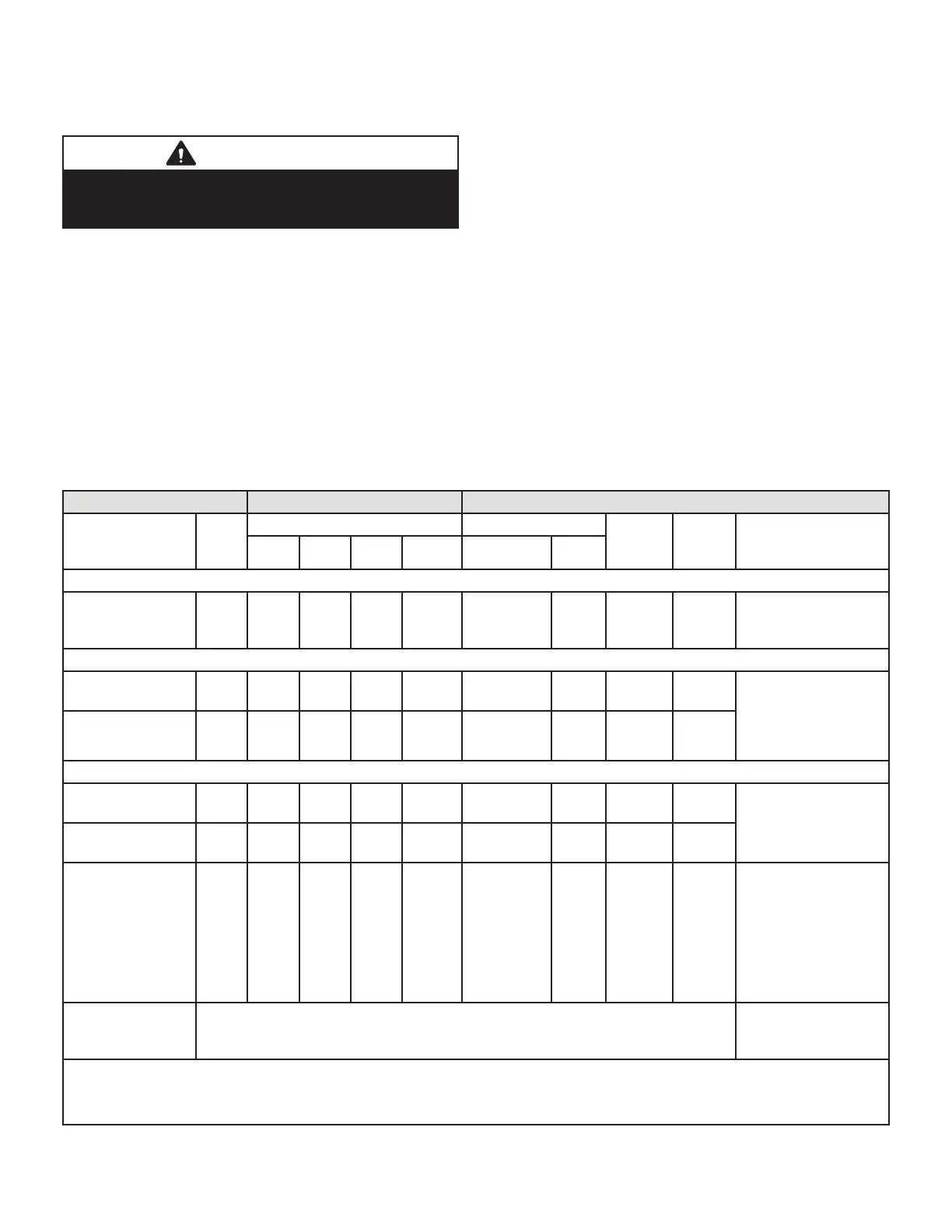
TABLE 12
OPERATING SEQUENCE
SL280UHV, Non-Communicating Thermostat with Humidity Control Feature and Single-Speed Outdoor Unit
OPERATING SEQUENCE SYSTEM DEMAND SYSTEM RESPONSE
System
Condition
Step
Thermostat Demand Relative Humidity
Compre
ssor
Blower
CFM
(cool)
Comments
Y1 O G W1 Status D
NO CALL FOR DEHUMIDIFICATION
Normal Operation 1 On On On Acceptable
24
VAC
High 100%
Compressor and
indoor blower follow
thermostat demand
BASIC MODE (only active on a Y1 thermostat demand)
Normal Operation 1 On On On Acceptable
24
VAC
High 100%
ComfortSense® 7500
thermostat energizes
Y1 and de-energizes
D on a call for de-
humidifi cation
Dehumidifi cation
call
2 On On On Demand 0 VAC High 70%*
PRECISION MODE (operates independent of a Y1 demand)
Normal Operation 1 On On On Acceptable
24
VAC
High 100%
Dehumidifi cation
mode begins when
humidity is greater
than set point
Dehumidifi cation
Call
2 On On On Demand 0 VAC High 70%*
Dehumidifi cation
Call Only
1 On On On Demand 0 VAC High 70%*
ComfortSense®
7500 thermostat will
try to maintain room
humidity setpoint by
allowing the room
space to maintain
a cooler room
thermostat setpoint**
Jumpers at indoor unit with a single stage outdoor unit. With Condensing unit - Cut
W914 (R to DS) on SureLight® control With Heat Pump - Cut W914 (R to DS) &
W951 (R to O) on SureLight® control
Dave Lennox ComfortSense® 7500 thermostat to use for this application - Y2081 4 heat / 2 cool
*Dehumidifi cation blower speed is 70% of COOL speed for all units .
**In Precision mode, ComfortSense® 7000 thermostat will maintain room temperature up to 2 °F (1.2°C) cooler than room setting.

 Loading...


