Page 50
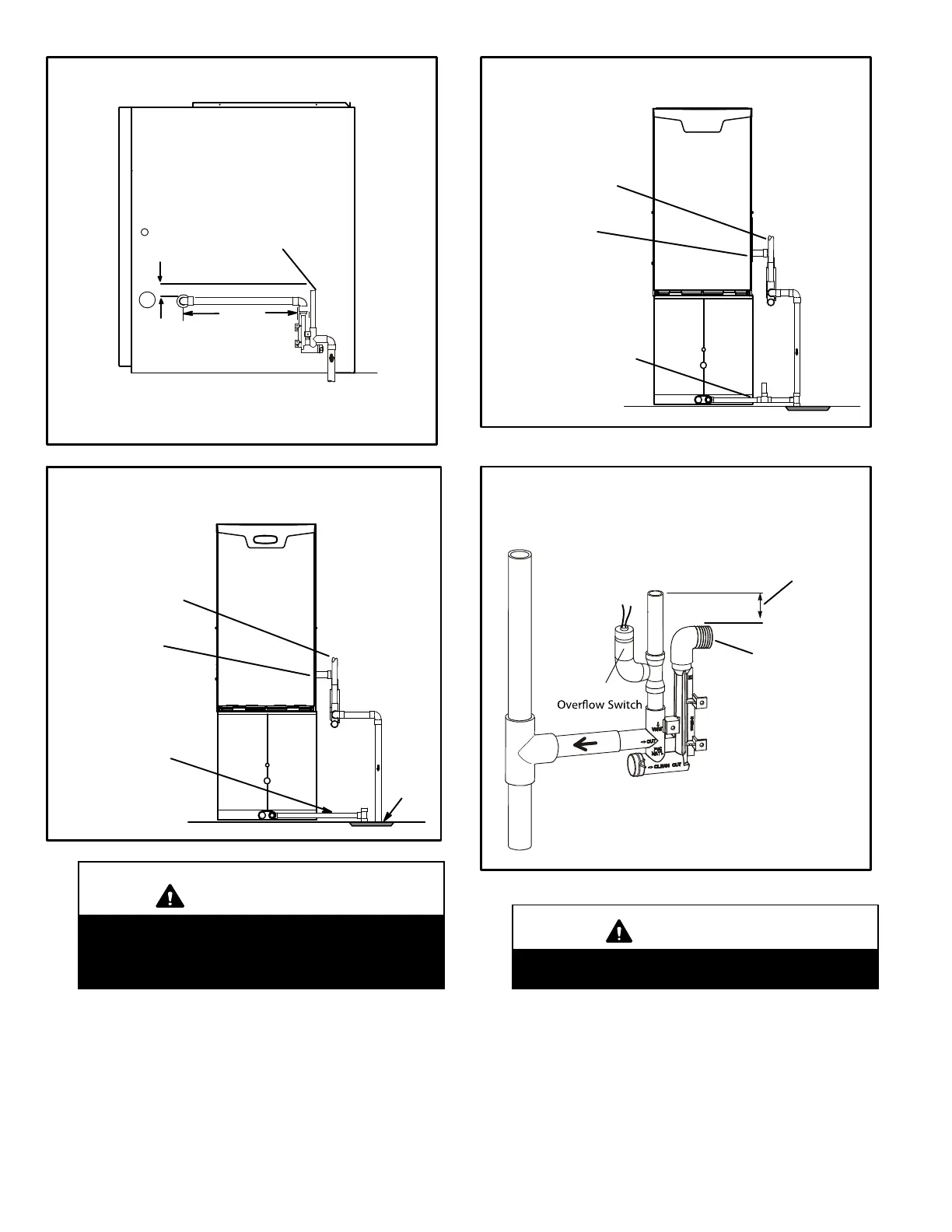
FIGURE 40
CONDENSATE TRAP LOCATION
(shown with right side exit of condensation)
5’ max.
to drain
1” min.
2” max.
Trap can be installed a maximum
of 5ft. from furnace (*PVC only)
Field Provided Vent
1” min. 2” max. above
condensate drain.
*Piping from furnace must slope down a
minimum 1/4” per ft. toward trap
FIGURE 41
SLP98DFV with Evaporator Coil
Using a Separate Drain
Drain
Field Provided Vent
1” min. 2” max. above
condensate drain.
Condensate Drain
Connection
Evaporator Drain Line
(vent required)
IMPORTANT
When combining the furnace and evaporator coil
drains together, the A/C condensate drain outlet
must be vented to relieve pressure in order for
the furnace pressure switch to operate properly.
FIGURE 42
SLP98DFV with Evaporator
Coil Using a Common Drain
Field Provided Vent
1” min. 2” max. above
condensate drain.
Evaporator Drain Line
(vent required)
Condensate Drain
Connection
FIGURE 43
FurnaceCondensate
Drain
Connection
From Evaporator Coil
Optional
Condensate Trap With Optional Overflow Switch
Field Provided Vent
1” min. 2” max. above
condensate drain.
CAUTION
Do not use copper tubing or existing copper con
densate lines for drain line.
 Loading...


