Page 34
II-icomfort Wi-Fi
®
thermostat (if applicable)
In communicating applications the Lennox icomfort Wi-Fi
®
thermostat must be used. In these applications the icomfort
Toucht thermostat overrides the DIP switch settings on the
integrated control. Refer to the illustrations provided with
the thermostat for installation, set-up and operation.
See figures 20 and 21 for icomfort Wi-Fi
®
thermostat wiring
in communicating applications.
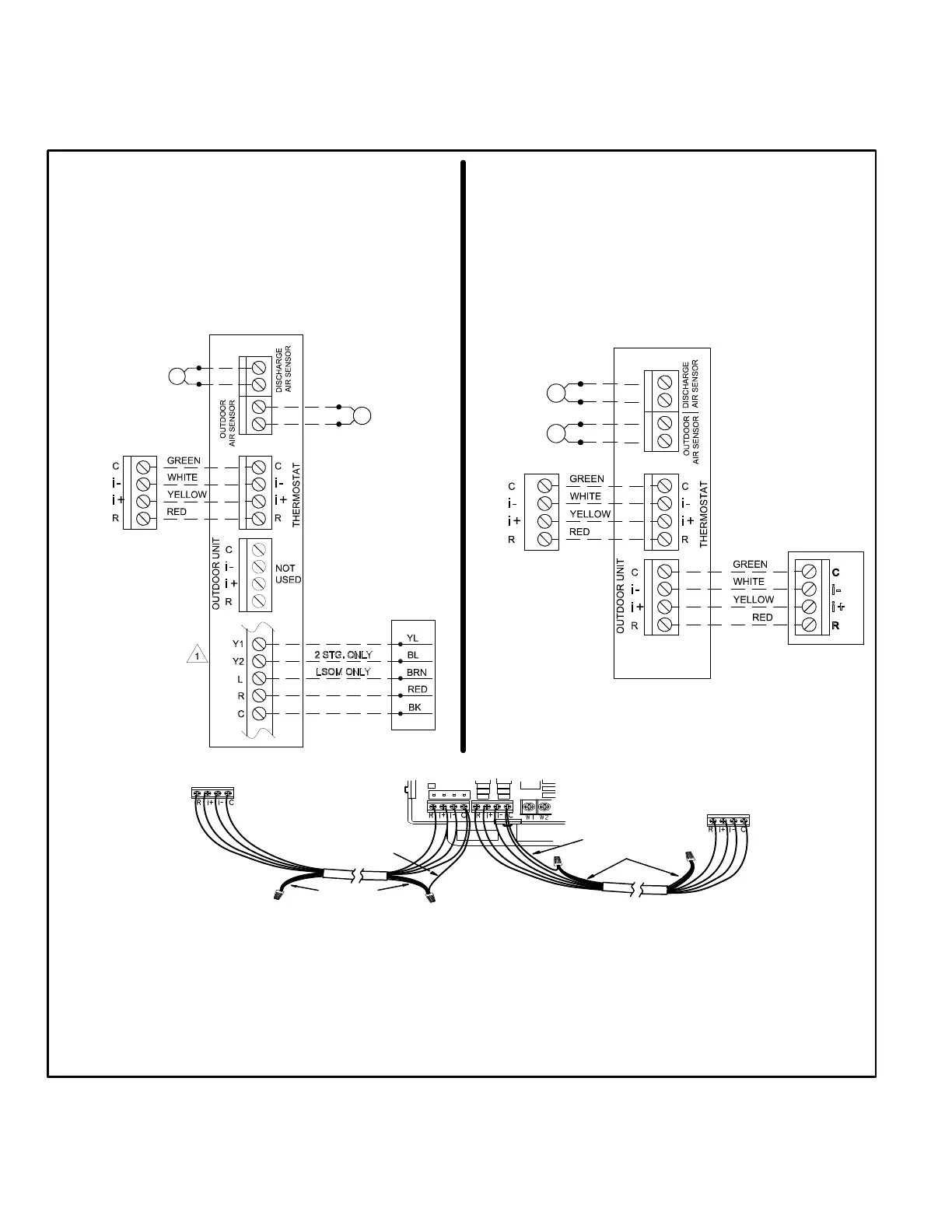
FIGURE 20
icomfort Wi-Fi
®
Thermostat with SLP98DFV
and Non-Communicating Outdoor Unit
icomfortt-
ENABLED
SLP98DFV
FURNACE
icomfort Wi-Fi
®
THERMOSTAT
NON-COMMUNICATING
OUTDOOR AIR
CONDITIONING UNIT -
1 OR 2 STAGE
icomfort Wi-Fi
®
Thermostat
icomfortt-Enabled SLP98DFV Indoor Furnace
Non-Communicating Outdoor Air Conditioner
OPTIONAL
OUTDOOR
AIR SENSOR
OPTIONAL
DISCHARGE
AIR SENSOR
icomfort Wi-Fi
®
Thermostat with SLP98DFV
and icomfort-ENABLED Outdoor Unit
icomfort Wi-Fi
®
Thermostat
icomfortt-Enabled SLP98DFV Indoor Furnace
icomfortt-Enabled Outdoor Air Conditioner or Heat Pump
icomfortt-
ENABLED
SLP98DFV
FURNACE
icomfortt- ENABLED
OUTDOOR AIR CONDITIONIN
OR HEAT PUMP UNIT
OPTIONAL
OUTDOOR
AIR SENSOR
OPTIONAL
DISCHARGE
AIR SENSOR
CLIP Y1 TO Y2 FOR
TWO-STAGE OPERATION
icomfort Wi-Fi
®
THERMOSTAT
Indoor Unit
Controller
Outdoor Unit
IcomfortWi-Fi
®
thermostat
Single wire to
terminal C
Single wire to
terminal C
Unused wires
Unused wires
Communicating systems using the IcomfortWi-Fi
®
thermostat require four ther
mostat wires between the thermostat and the furnace/air handler control and four
wires between the outdoor unit and the furnace/air handler control. When a ther
mostat cable with more than four wires is used, the extra wires must be properly
connected to avoid electrical noise. The wires must not be left disconnected.
Use wire nuts to bundle the four unused wires at each end of the cable. A
single wire should then be connected to the indoor unit end of the wire bundle
and attached to the “C” terminals as shown in the diagram above.
 Loading...


