Page 65
E- Proper Gas Flow (Approximate)
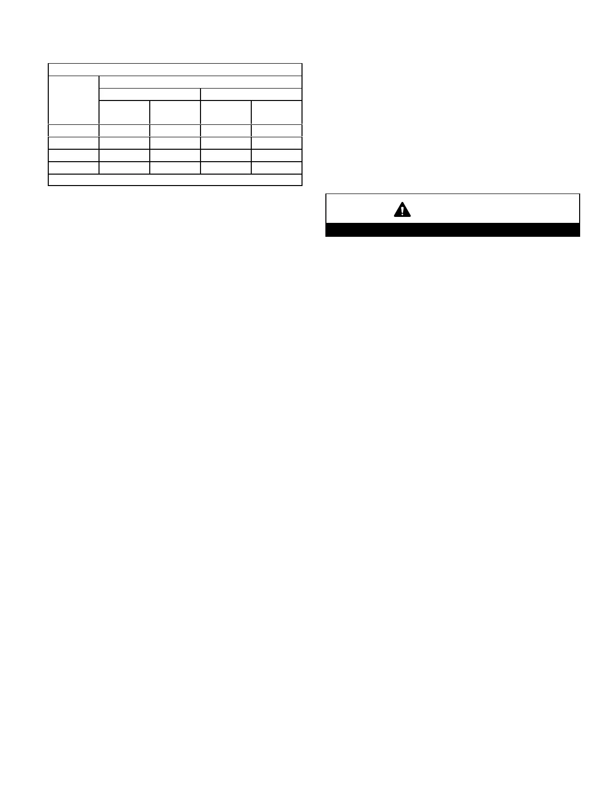
TABLE 28
GAS METER CLOCKING CHART
SLP99
Unit
Seconds for One Revolution
Natural LP
1 cu ft
Dial
2 cu ft
Dial
1 cu ft
Dial
2 cu ft
DIAL
-70 55 110 136 272
-90 41 82 102 204
-110 33 66 82 164
-135 27 54 68 136
Natural-1000 btu/cu ft LP-2500 btu/cu ft
Furnace should operate at least 5 minutes before checking
gas flow. Determine time in seconds for two revolutions of
gas through the meter. (Two revolutions assures a more
accurate time.) Divide by two and compare to time in
table 28. If manifold pressure matches table 32 and rate is
incorrect, check gas orifices for proper size and restriction.
NOTE - To obtain accurate reading, shut off all other gas ap
pliances connected to meter.
F-Check Manifold Pressure (Figure 51)
To correctly measure manifold pressure, the differential
pressure between the positive gas manifold and the nega
tive burner box must be considered. Use pressure test
adapter kit (available as Lennox part 10L34) to assist in
measurement.
1 - Connect test gauge “+” connection to manifold pres
sure tap on the gas valve.
2 - Tee into the gas valve regulator vent hose and con
nect test gauge “-” connection.
3 - Start unit on low heat (35% rate) and allow 5 minutes
for unit to reach steady state.
4 - While waiting for the unit to stabilize, notice the
flame. Flame should be stable and should not lift from
burner. Natural gas should burn blue.
5 - After allowing unit to run for 5 minutes, record man
ifold pressure and compare to value given in table 32.
6 - Repeat steps 3, 4 and 5 on high fire.
7 -Shut unit off and remove manometer as soon as an
accurate reading has been obtained. Take care to re
move barbed fitting and replace threaded plug.
8 -Start unit and perform leak check. Seal leaks if
found.
CAUTION
Do not attempt to make adjustments to the gas valve.
G-Operating Pressure Signal (Delta P) Measurement
(Figure 52)
Operating pressure signal can be taken while the manifold
pressure pressure check is taken (using two measuring de
vices). Or, taken after the manifold pressure measurement
is complete.
1 - Tee into the negative line between the gas valve and
pressure switch and connect to measuring device neg
ative “-”.
2 - Tee into the positive line between the gas valve and
pressure switch and connect to measuring device posi
tive “+”.
3 - Start unit on low heat (35% rate) and allow 5 minutes
for unit to reach steady state.
4 - After allowing unit to stabilize for 5 minutes, record op
erating pressure signal and compare to value given in
table 32.
5 - Repeat steps 3 on 4 high heat.

 Loading...


