Page 37
BLOWER B3 HARNESS CONNECTORS
MOTOR with INTEGRATED
CONTROLLER
SHAFT
P49 4 Pin
P48 5 Pin
P48 5 Pin
P49 4 Pin
J48 Connector
installed on motor
P49 4 Pin
120v
0
240v
5
4
3
2
1
J48 Connector
24v Transformer
J49 Connector
FIGURE 10
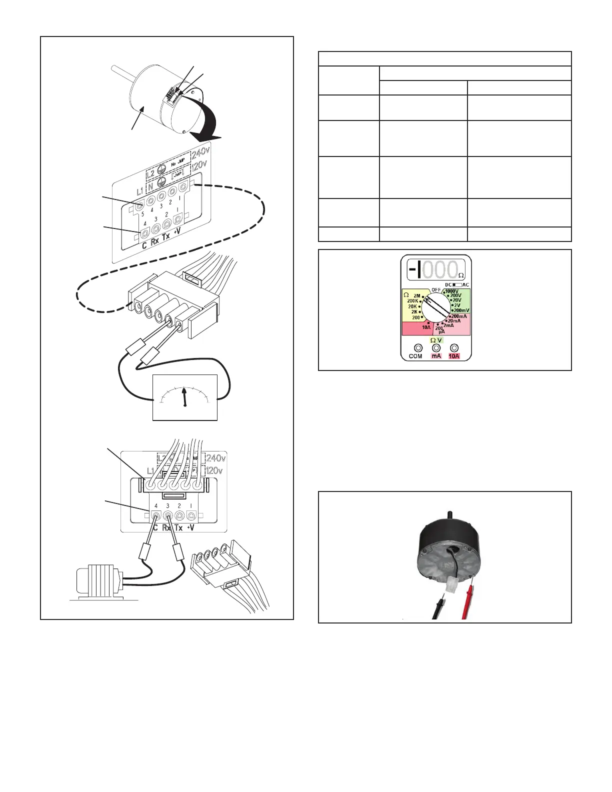
Troubleshooting Motor Windings
Ensure that motor windings are not damaged by perform-
ing the following tests:
NOTE - If your ohm meter is not an auto-ranging type, set
it to the highest ohm scale (100k ohms or greater) before
performing tests.
TABLE 17
Ohm Meter Range
Scale Measurement Range
In Words ohms
2M two megohm - two
million ohms
0 - 2,000,000
200k two hundred kilohm
- two hundred
thousand ohms
0 - 200,000
20k twenty kilohm --
twenty thousand
ohms
0-20,000
2k two kilohm -- two
thousand ohms
0 - 2,000
200 two hundred ohm 0 - 200
FIGURE 11
TEST A
Measure the resistance between each of the three motor
leads (3-pin plug) and the unpainted part of the end shield.
If the winding resistance to ground is <100k ohms,
replace the motor and control module. If the resistance
to ground is >100k, the motor windings are ne.
Proceed to Test B.
FIGURE 12

 Loading...


