Page 38
TEST B
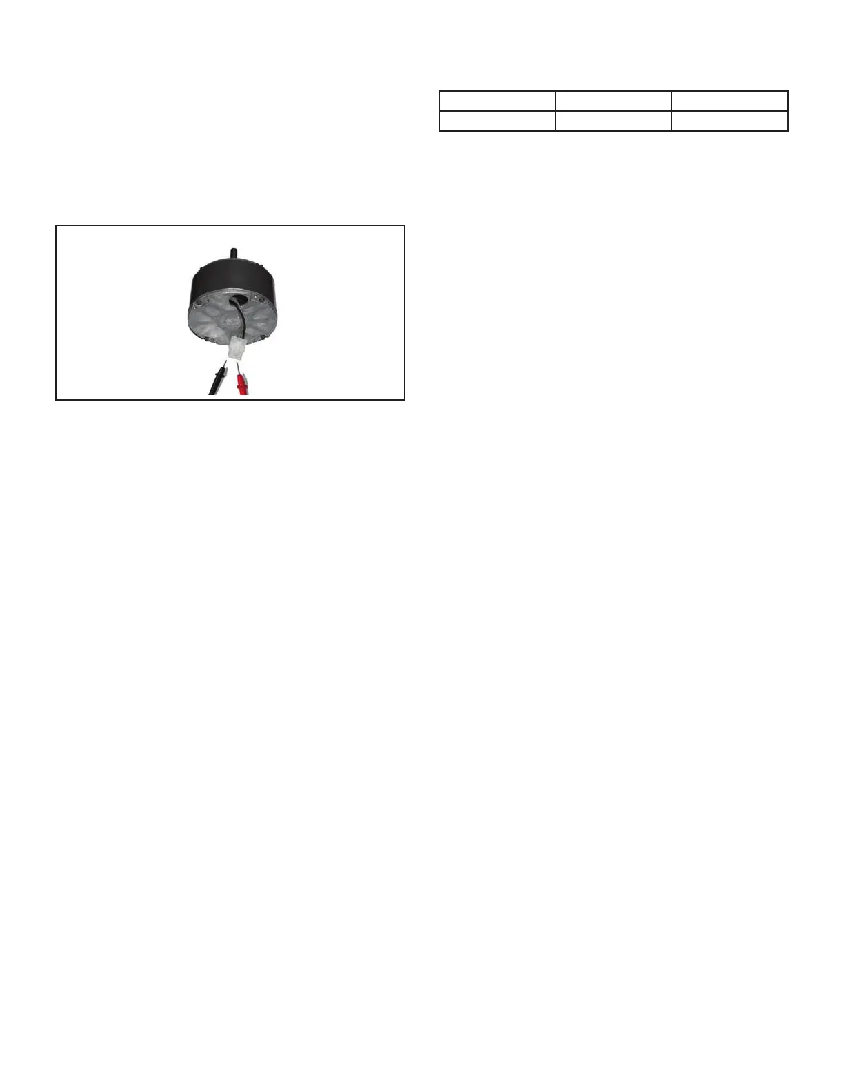
Use an ohmmeter to measure the motor phase-to-phase
resistance by checking these combinations of the the 3-pin
motor plug. For the purpose of this test, start at either end
of the connector as lead 1.
1 - The lead-to-lead resistance across any two leads
should be less than 20 ohms.
2 - Each lead-to-lead resistance should be the same.
If the measured resistance is greater than 20 ohms, re-
place the motor and control module.
FIGURE 13
C-Heating Components
Heating component locations are shown in FIGURE 14.
Make note the cover plate for the -090XV60C model only.
The cover plate is removed for LP/Propane conversion
only.
1. Ignitor
The SureLight
®
ignitor is made of durable silicon nitride.
Ignitor longevity is enhanced by controlling voltage to
the ignitor. The integrated control provides 120 volts to
the ignitor for a consistent ignition. Due to this feature of
the control, voltage measured with a digital meter will be
slightly lower. To measure correct voltage use a true RMS
meter or ignitor can be ohmed. Ohm value should be 39
to 70.
2. Flame Sensor
A ame sensor (FIGURE 14) is located on the left side of
the burner support. The sensor is mounted on the ame
rollout plate and the tip protrudes into the ame envelope
of the left-most burner. The sensor can be removed for
service without removing any part of the burners. During
operation, ame is sensed by current passed through the
ame and sensing electrode. The SureLight control allows
the gas valve to remain open as long as ame signal is
sensed. To check ame sense signal use the push-button
found on the integrated control and go to Field Test Mode.
The menu will display the ame signal. TABLE 18 shows
the ame signal for the SLP99UHV unit.
TABLE 18
Flame Signal in Microamps
Normal Low Drop Out
2.6 or greater 2.5 or less 1.1
NOTE - A much higher than normal micro amp reading
(15 for example) may appear when checking ame signal.
3. Flame Rollout Switches
Flame rollout switch S47 is a high temperature limit located
inside the burner box. Each furnace is equipped with two
identical switches. The limit is a N.C. SPST manual-reset
limit connected in series with the primary limit S10. When
S47 senses rollout, the circuit breaks and the integrat-
ed control immediately stops ignition and closes the gas
valve. If unit is running and ame rollout is detected, the
gas valve will close and integrated control will be disabled.
Rollout can be caused by a blocked heat exchanger, ue
or lack of combustion air. The switch is factory set to trip
(open) at 210°F and cannot be adjusted. The switch can
be manually reset. To manually reset a tripped switch,
push the reset button located on the center of the switch.
4. Burners
All units use inshot burners. Burners are factory set and
require no adjustment. Always operate the unit with the
burner box front panel in place. Each burner uses an ori-
ce that is precisely matched to the burner input. Burners
can be removed as a one piece assembly for service. If
burner assembly has been removed, it is critical to align
center of each burner to the center of the clamshell when
re-installing. See more detail in Section VII- MAINTE-
NANCE..
5. Duralock Plus Heat Exchanger (FIGURE 15)
SLP99UHV units use an aluminized steel primary and
stainless steel secondary heat exchanger assembly. Heat
is transferred to the air stream from all surfaces of the heat
exchanger. The shape of the heat exchanger ensures
maximum eciency.
The combustion air inducer pulls fresh air through the
burner box. This air is mixed with gas in the burners. The
gas / air mixture is then burned at the entrance of each
clamshell. Combustion gases are then pulled through the
primary and secondary heat exchangers and exhausted
out the exhaust vent pipe.

 Loading...


