Page 43
1 -Remove thermostat demand and allow unit to cycle off.
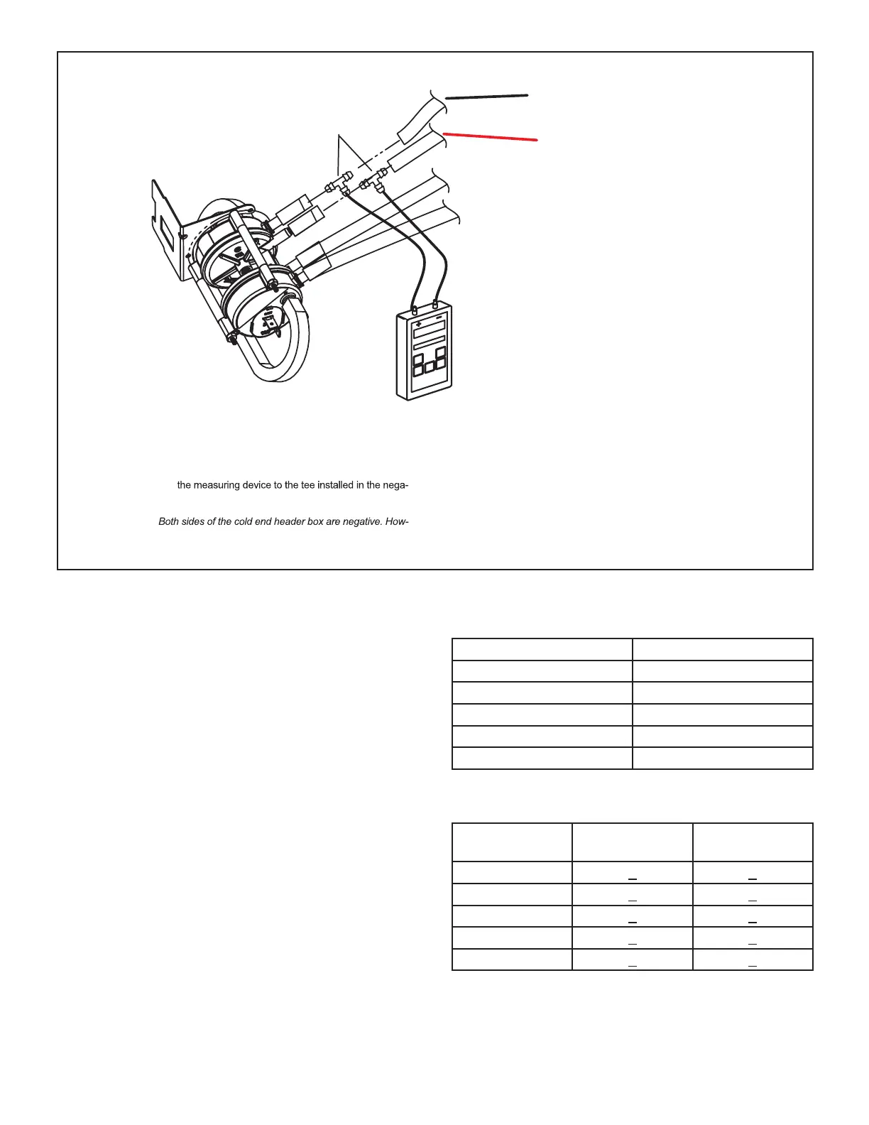
2 -Install a tee in the negative (-) line (red and black tubing or red
tubing) and a tee in the positive (+) line (black tubing) running
from the pressure switch to the cold end header box.
3 - Install a measuring device with hose from the negative (-)
side of
tive (-) line and with hose from the positive (+) side of the
measuring device to the tee in the positive (+) line.
NOTE -
ever the (+) port reads less negative pressure than the (-) port.
4 -Operate unit and observe measuring device reading.
Readings will change as heat exchanger warms.
a. Take one reading immediately after start‐up.
b. Take a second reading after unit has reached steady
state (approximately 5 minutes). This will be the pressure
differential.
The pressure differential should be greater
than those listed in table 20.
5 -Remove thermostat demand and allow to cycle off.
6 -Remove measuring device and tee's. Reinstall combustion
air sensing hoses to the pressure switch.
RED and BLACK TUBING
or RED TUBING NEGATIVE
BLACK TUBING
POSITIVE
Measuring Pressure Differential
To Cold End Header Box
Field Installed
Measuring Device
Red
FIGURE 18
The CAI is installed on the cold end header box. The cold
end header box is a single piece made of hard plastic.
The box has an internal channel where the combustion
air inducer creates negative pressure at unit start up. The
channel contains an orice used to regulate ow created
by the CAI. The box has pressure taps for the CAI pres-
sure switch hoses.
The pressure switch measures the pressure dierential
across the CAI orice (dierence in the channel and cold
end header box). See TABLE 19 for orice size per unit.
If replacement is necessary the gaskets used to seal
the box to the vestibule panel and the CAI to the box,
must also be replaced.
TABLE 19
SLP99UHV Unit C.A.I Orice
-070 0.775
-09036C/48C 0.890
-09060C 0.840
-110 1.000
-135 1.100
TABLE 20
Pressure Switch 0’ to 7500’
SLP99UHV
Set Point High
Fire
Set Point Low
Fire
-070
1.00 + 0.05 0.25 + 0.05
-09036C/48C
1.00 + 0.05 0.25 + 0.05
-09060C
1.00 + 0.05 0.15 + 0.05
-110
1.00 + 0.05 0.25 + 0.05
-135
1.00 + 0.05 0.25 + 0.05
*Units over 7500 ft will require a conversion kit. See table
31.

 Loading...


