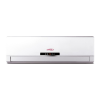
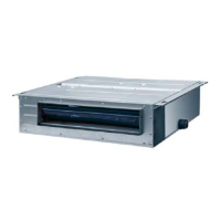
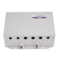
DC Inverter Multi VRF System
23
(2) Selection of circuit breaker and power cord.
Model Power supply
Circuit breaker
capacity
Number of ground
wire× Min sectional
2
Number of power cord
× Min sectional area
2
VEP027N432US
220~240V 50Hz
25 1×2.5 2×2.5
VEP034N432US
220~240V 50Hz
208~230V 60Hz
25 1×2.5 2×2.5
VEP042N432US
220~240V 50Hz
32 1×2.5 2×2.5
VEP042N432U
220~240V 50Hz
208~230V 60Hz
32 1×2.5 2×2.5
VEP048N432US
220~240V 50Hz
40 1×6.0 2×6.0
VEP048N432U
220~240V 50Hz
208~230V 60Hz
40 1×6.0 2×6.0
VEP060N432U
220~240V 50Hz
40 1×6.0 2×6.0
NOTES:
①
Selection of circuit breaker and power cord in the above table is based upon unit’s maximum
power (maximum current).
②
Specification of power cord is based on the working condition where ambient temperature is
40°C and multi-core copper cable (working temperature is 90°C, e.g. power cable with YJV
cross-linked copper, insulated PE and PVC sheath) is lying on the surface of slot. If working
condition changes, please adjust the specification according to national standard.
③
Specification of circuit breaker is based on the working condition where ambient temperature
of circuit breaker is 40°C. If working condition changes, please adjust the specification
according to national standard.

 Loading...


