27
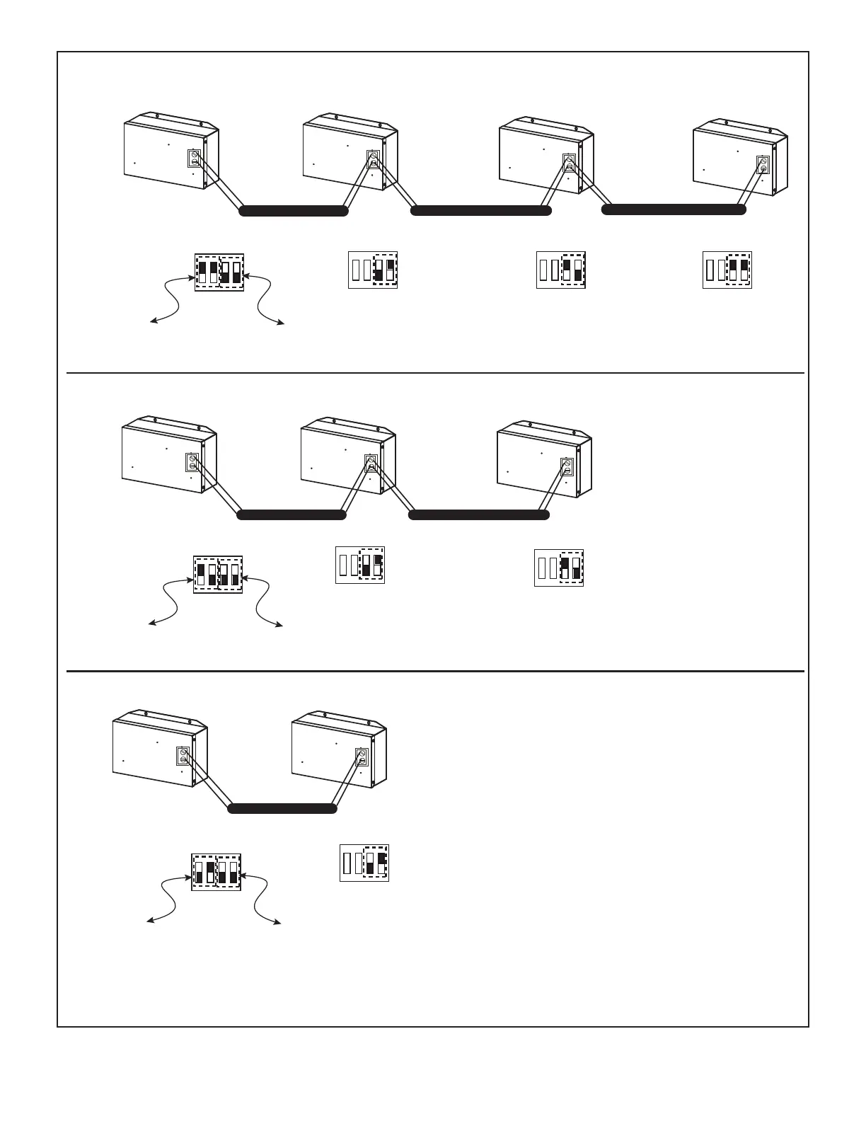
Figure 20. Parallel AHU Control Kit Congurations
Main kit Sub kit 1 Sub kit 2 Sub kit 3
ON
1 2 3 4
SW2
ON
1 2 3 4
SW2
ON
1 2 3 4
SW2
X
Y
X
Y
X
Y
X
Y
ON
1 2 3 4
SW2
11: Quantity of sub-kits is 3
(total quantity of kits is 4)
ON
1 2 3 4
SW2
01: Sub kit
address is 1
ON
1 2 3 4
SW2
ON
1 2 3 4
SW2
Main kit Sub kit 1 Sub kit 2
X
Y
X
Y
X
Y
Main kit Sub kit 1
X
Y
X
Y
00: Main kit
address is 0
10: Sub kit
address is 2
11: Sub kit
address is 3
01: Sub kit
address is 1
10: Sub kit
address is 2
01: Sub kit
address is 1
ON
1 2 3 4
SW2
10: Quantity of sub-kits is 2
(total quantity of kits is 3)
00:Main kit
address is 0
ON
1 2 3 4
SW2
01: Quantity of sub-kits is 1
(total quantity of kits is 2)
00:Main kit
address is 0
NOTE - A maximum of four AHU Control Kits can be connected in parallel. Congure dip switch SW2 per this diagram.
 Loading...