EasyManua.ls Logo

Lennox XC13-024-230-01 User Manual

Lennox XC13-024-230-01
30 pages
To Next Page IconTo Next Page
Page #1 background imageLoading...
Page #1 background image
07/11 506636−01
*2P0711* *P506636-01*
Page 1
201 Lennox Industries Inc.
Dallas, Texas, USA
RETAIN THESE INSTRUCTIONS
FOR FUTURE REFERENCE
These instructions are intended as a general guide and do
not supersede local codes in any way. Consult authorities
having jurisdiction before installation.
WARNING
Improper installation, adjustment, alteration, service or
maintenance can cause personal injury, loss of life, or
damage to property.
Installation and service must be performed by a licensed
professional installer (or equivalent) or a service agency.
IMPORTANT
The Clean Air Act of 1990 bans the intentional venting of
refrigerant (CFCs, HCFCs and HFCs) as of July 1, 1992.
Approved methods of recovery, recycling or reclaiming
must be followed. Fines and/or incarceration may be
levied for noncompliance.
IMPORTANT
This unit must be matched with an indoor coil as speci-
fied in Lennox XC14 Engineering Handbook. Coils pre-
viously charged with HCFC−22 must be flushed.
NOTICE TO INSTALLER
UNIT PLACEMENT
It is critical for proper unit operation to place outdoor unit on an
elevated surface as described in Unit Placement section on page 7.
BRAZING LINE SET TO SERVICE VALVES
It is imperative to follow the brazing technique illustrated starting on
page 12 to avoid damaging the service valve’s internal seals.
INSTALLATION
INSTRUCTIONS
Elite
®
Series XC14 Units
AIR CONDITIONER
506636−01
07/11
Supersedes 11/10
TABLE OF CONTENTS
General 1. . . . . . . . . . . . . . . . . . . . . . . . . . . . . . . . . . . . . .
Shipping and Packing List 1. . . . . . . . . . . . . . . . . . . . . .
Unit Dimensions 2. . . . . . . . . . . . . . . . . . . . . . . . . . . . . . .
Model Number Identification 2. . . . . . . . . . . . . . . . . . . .
Unit Parts Arrangement 3. . . . . . . . . . . . . . . . . . . . . . . .
Operating Gauge Set and Service Valves 4. . . . . . . . .
Recovering Refrigerant from Existing System 6. . . . .
Unit Placement 7. . . . . . . . . . . . . . . . . . . . . . . . . . . . . . . .
Removing and Installing Panels 9. . . . . . . . . . . . . . . . .
New or Replacement Line Set 10. . . . . . . . . . . . . . . . . . .
Brazing Connections 12. . . . . . . . . . . . . . . . . . . . . . . . . . .
Flushing Line Set and Indoor Coil 15. . . . . . . . . . . . . . . .
Installing Indoor Metering Device 16. . . . . . . . . . . . . . . .
Leak Test Line Set and Indoor Coil 17. . . . . . . . . . . . . . .
Evacuating Line Set and Indoor Coil 18. . . . . . . . . . . . .
Electrical 19. . . . . . . . . . . . . . . . . . . . . . . . . . . . . . . . . . . . .
Servicing Units Delivered Void of Charge 23. . . . . . . . .
Unit Start−Up 23. . . . . . . . . . . . . . . . . . . . . . . . . . . . . . . . . .
System Refrigerant 23. . . . . . . . . . . . . . . . . . . . . . . . . . . .
System Operation 28. . . . . . . . . . . . . . . . . . . . . . . . . . . . .
Maintenance 29. . . . . . . . . . . . . . . . . . . . . . . . . . . . . . . . . .
Start−Up and Performance Checklist 30. . . . . . . . . . . . .
General
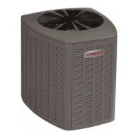
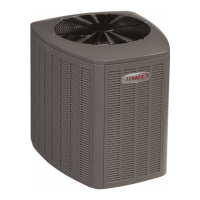
The XC14 Air Conditioners, which will also be referred to in
this instruction as the outdoor unit, uses HFC−410A
refrigerant. This outdoor unit must be installed with a
matching indoor unit and line set as outlined in the Lennox
XC14 Engineering Handbook.
Shipping and Packing List
Check the unit for shipping damage and listed times below
are intact. If damaged, or if parts are missing, immediately
contact the last shipping carrier.
1  Assembled outdoor unit.
1  Refrigerant flow control (RFC) kit (Fixed Orifice)
Litho U.S.A.
Question and Answer IconNeed help?

Do you have a question about the Lennox XC13-024-230-01 and is the answer not in the manual?

Lennox XC13-024-230-01 Specifications

General IconGeneral
Model NumberXC13-024-230-01
CategoryAir Conditioner
Voltage230V
RefrigerantR-410A
Sound Level (Outdoor Unit)74 dB
Phase1
Cooling Capacity24000 BTU
Compressor TypeSingle Stage

Summary

General System Information

Shipping and Packing List

Unit Dimensions

Model Number Identification

Typical Unit Parts Arrangement

Operating Gauge Set and Service Valves

Torque Requirements

Lists recommended torque values for various fasteners.

Using Manifold Gauge Set

Details requirements for using manifold gauge sets with HFC-410A.

Operating Service Valves

Explains the use of liquid and vapor line service valves.

Service Valve Operation Details

Operating Angle Type Service Valve

Details how to operate the angle type service valve.

Operating Ball Type Service Valve

Details how to operate the ball type service valve.

Accessing Service Ports

Explains how to access and seal service ports.

Recovering Refrigerant from Existing System

Disconnect Power

Step to disconnect all power to the outdoor unit.

Connect Manifold Gauge Set

Connects gauge set, recovery cylinder, and machine.

Recovering Refrigerant

Details methods for removing HCFC-22 refrigerant.

Unit Placement

Positioning Considerations

Discusses sound ordinances and window placement.

Slab Mounting

Instructions for placing the unit on a grade-level slab.

Elevating the Unit

Guidance on raising the unit using support feet extenders.

Roof Mounting

Notice - Roof Damage!

Warns about oil damage to rubber roofing materials.

Removing and Installing Panels

Louvered Panel Removal

Steps for removing louvered panels from the unit.

Louvered Panel Installation

Steps for installing louvered panels onto the unit.

New or Replacement Line Set

Refrigerant Line Set

Provides information on installing or replacing refrigerant line sets.

Refrigerant Line Set Table

Details line set sizes and recommendations by model number.

Line Set Isolation

Transition from Vertical to Horizontal

Illustrates methods for isolating line sets transitioning vertically to horizontally.

Installing Vertical Runs

Shows proper installation techniques for vertical refrigerant line runs.

Installing Horizontal Runs

Illustrates methods for isolating horizontal refrigerant line runs.

Brazing Connections

Safety and Recommendations

Covers safety warnings and alloy recommendations for brazing.

Brazing Procedures

Line Preparation and Gauge Setup

Covers cutting, core removal, and manifold gauge set connection.

Nitrogen Flow and Protection

Details nitrogen flow and protecting components during brazing.

Brazing Execution

Valve Protection and Cooling

Protecting service valves with wet cloths and cooling the joint.

Brazing the Line Set

The core procedure for brazing the refrigerant line set.

Flushing Line Set and Indoor Coil

Flushing Procedures

Details procedures for flushing fixed orifice or expansion valve systems.

Connecting Gauges and Equipment

How to connect equipment for the flushing procedure.

Flushing Line Set

Steps for flushing the line set and indoor unit coil.

Installing Indoor Metering Device

Indoor Expansion Valve Installation

Steps for installing an indoor expansion valve.

Sensing Bulb Installation

How to properly position and install the sensing bulb.

Equalizer Line Installation

Procedure for connecting the equalizer line.

Leak Test Line Set and Indoor Coil

Important Notes

EPA regulations and POE oil compatibility warnings.

Test for Leaks

Step-by-step procedure for performing a leak test.

Evacuating Line Set and Indoor Coil

Connect Gauge Set

How to connect the gauge set and vacuum pump.

Evacuate the System

Procedure for evacuating the system to the required micron level.

Electrical

Size Circuit and Install Disconnect Switch

Guidance on selecting and installing disconnect switches.

Install Thermostat

Recommendations for thermostat installation location.

Unit Low Voltage Connections

Wiring instructions for low voltage control connections.

Servicing Units Delivered Void of Charge

Leak Check System

Procedure for performing a system leak check.

Evacuate System

Procedure for evacuating the system.

Nitrogen Purge and Filter Drier Replacement

Using nitrogen to break vacuum and replace filter drier.

Unit Start-Up

Crankcase Heater Energization

Importance of energizing the crankcase heater before start-up.

Pre-Start Checks

Checks for fan binding, wiring, voltage, and disconnects.

System Refrigerant

Procedures for connecting gauges, checking airflow, and adding refrigerant.

Determining Charge Method

When to Charge

Conditions and requirements for charging the system.

Charge Method Determination

Determining charge method based on metering device and temperature.

Checking Air Flow at Indoor Coil

Delta-T Process

Using the Delta-T chart to check indoor airflow.

Adjusting Airflow

How to adjust fan speed based on airflow checks.

Weigh In Charging Method

Calculating System Charge

Formula for calculating total refrigerant charge.

Refrigerant Charge per Line Set Length

Table for adjusting charge based on line set length.

Approach TXV Charge Method

Determine Approach Value

Steps to calculate and compare approach values for TXV systems.

Subcooling TXV Charge Method

Determine Subcooling Value

Steps to calculate and compare subcooling values for TXV systems.

Superheat RFC Charge Method

Determine Superheat Value

Steps to calculate and compare superheat values for fixed orifice systems.

Unit Components

High Pressure Switch (S4)

Function and operation of the high pressure switch.

Thermal Protection Switch (S5) — Discharge Line Mounted

Function of the discharge line temperature protection switch.

Thermal Protection Switch (S173) - Compressor Mounted

Function of the compressor casing temperature protection switch.

Crankcase Thermostat (S40)

Function of the crankcase heater thermostat.

Maintenance

Dealer Maintenance (Outdoor Unit)

Tasks for dealers to perform on the outdoor unit.

Dealer Maintenance (Indoor Unit)

Tasks for dealers to perform on the indoor unit.

Homeowner Maintenance

Maintenance tasks homeowners can perform.

Outdoor Coil Maintenance

Specific cleaning and inspection requirements for the outdoor coil.

Thermostat Operation

Preservice Check

Pre-checks before calling for service if the system fails.

Accessories

List of related publications for more information.

Start-Up and Performance Checklist

Checklist Items

List of checks for proper installation and operation.

Related product manuals