EasyManua.ls Logo

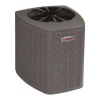
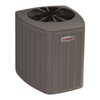
Lennox XC13-036-230-07 User Manual

Lennox XC13-036-230-07
30 pages
To Next Page IconTo Next Page
Page #1 background imageLoading...
Page #1 background image
07/11 506636−01
*2P0711* *P506636-01*
Page 1
201 Lennox Industries Inc.
Dallas, Texas, USA
RETAIN THESE INSTRUCTIONS
FOR FUTURE REFERENCE
These instructions are intended as a general guide and do
not supersede local codes in any way. Consult authorities
having jurisdiction before installation.
WARNING
Improper installation, adjustment, alteration, service or
maintenance can cause personal injury, loss of life, or
damage to property.
Installation and service must be performed by a licensed
professional installer (or equivalent) or a service agency.
IMPORTANT
The Clean Air Act of 1990 bans the intentional venting of
refrigerant (CFCs, HCFCs and HFCs) as of July 1, 1992.
Approved methods of recovery, recycling or reclaiming
must be followed. Fines and/or incarceration may be
levied for noncompliance.
IMPORTANT
This unit must be matched with an indoor coil as speci-
fied in Lennox XC14 Engineering Handbook. Coils pre-
viously charged with HCFC−22 must be flushed.
NOTICE TO INSTALLER
UNIT PLACEMENT
It is critical for proper unit operation to place outdoor unit on an
elevated surface as described in Unit Placement section on page 7.
BRAZING LINE SET TO SERVICE VALVES
It is imperative to follow the brazing technique illustrated starting on
page 12 to avoid damaging the service valve’s internal seals.
INSTALLATION
INSTRUCTIONS
Elite
®
Series XC14 Units
AIR CONDITIONER
506636−01
07/11
Supersedes 11/10
TABLE OF CONTENTS
General 1. . . . . . . . . . . . . . . . . . . . . . . . . . . . . . . . . . . . . .
Shipping and Packing List 1. . . . . . . . . . . . . . . . . . . . . .
Unit Dimensions 2. . . . . . . . . . . . . . . . . . . . . . . . . . . . . . .
Model Number Identification 2. . . . . . . . . . . . . . . . . . . .
Unit Parts Arrangement 3. . . . . . . . . . . . . . . . . . . . . . . .
Operating Gauge Set and Service Valves 4. . . . . . . . .
Recovering Refrigerant from Existing System 6. . . . .
Unit Placement 7. . . . . . . . . . . . . . . . . . . . . . . . . . . . . . . .
Removing and Installing Panels 9. . . . . . . . . . . . . . . . .
New or Replacement Line Set 10. . . . . . . . . . . . . . . . . . .
Brazing Connections 12. . . . . . . . . . . . . . . . . . . . . . . . . . .
Flushing Line Set and Indoor Coil 15. . . . . . . . . . . . . . . .
Installing Indoor Metering Device 16. . . . . . . . . . . . . . . .
Leak Test Line Set and Indoor Coil 17. . . . . . . . . . . . . . .
Evacuating Line Set and Indoor Coil 18. . . . . . . . . . . . .
Electrical 19. . . . . . . . . . . . . . . . . . . . . . . . . . . . . . . . . . . . .
Servicing Units Delivered Void of Charge 23. . . . . . . . .
Unit Start−Up 23. . . . . . . . . . . . . . . . . . . . . . . . . . . . . . . . . .
System Refrigerant 23. . . . . . . . . . . . . . . . . . . . . . . . . . . .
System Operation 28. . . . . . . . . . . . . . . . . . . . . . . . . . . . .
Maintenance 29. . . . . . . . . . . . . . . . . . . . . . . . . . . . . . . . . .
Start−Up and Performance Checklist 30. . . . . . . . . . . . .
General
The XC14 Air Conditioners, which will also be referred to in
this instruction as the outdoor unit, uses HFC−410A
refrigerant. This outdoor unit must be installed with a
matching indoor unit and line set as outlined in the Lennox
XC14 Engineering Handbook.
Shipping and Packing List
Check the unit for shipping damage and listed times below
are intact. If damaged, or if parts are missing, immediately
contact the last shipping carrier.
1  Assembled outdoor unit.
1  Refrigerant flow control (RFC) kit (Fixed Orifice)
Litho U.S.A.
Question and Answer IconNeed help?

Do you have a question about the Lennox XC13-036-230-07 and is the answer not in the manual?

Lennox XC13-036-230-07 Specifications

General IconGeneral
Compressor TypeScroll
RefrigerantR-410A
Sound Level74 dB
Phase1
Hertz60 Hz
Sound Level (Outdoor Unit)74 dB
Cooling Capacity36, 000 BTU/h
SEER Rating13
Voltage230 V

Summary

General

Shipping and Packing List

Unit Dimensions

Model Number Identification

Identifies the unit's model number and its components for proper selection and reference.

Typical Unit Parts Arrangement

Operating Gauge Set and Service Valves

Torque Requirements

Specifies torque values for various fasteners during installation and service to ensure proper assembly.

Using Manifold Gauge Set

Details the proper use of manifold gauge sets with HFC-410A systems for diagnostics and charging.

Operating Service Valves

Explains how to access and operate service valves for system maintenance and refrigerant handling.

Operating Angle Type Service Valve

Describes how to operate angle-type service valves for proper system access and control.

Operating Ball Type Service Valve

Details the operation of ball-type service valves for system manipulation.

To Access Service Port

Instructions on accessing the service port for connecting testing and charging equipment.

Reinstall Stem Cap

Guides on properly reinstalling service valve stem caps to ensure a seal.

Recovering Refrigerant from Existing System

Unit Placement

Positioning Considerations

Factors to consider when choosing the unit's placement location for optimal performance and noise.

Placing Unit on Slab

Instructions for setting up the unit on a foundation slab to ensure stability and levelness.

Elevating the Unit

Methods for raising the unit using extenders for proper height and clearance.

Outside Unit Placement Details

Illustrates proper placement of the outdoor unit away from windows for optimal operation.

Slab Mounting Details

Explains slab mounting and slope tolerance for ground-level unit installations.

Elevated Slab Mounting Details

Shows how to use feet extenders for elevated slab mounting and leveling.

Slab Side Mounting Details

Describes side mounting to a slab using brackets for stability.

Deck Top Mounting Details

Illustrates the procedure for mounting the unit on a deck.

Roof Mounting

Roof Damage Notice

Warns about potential damage to roofing material from oil and refrigerant exposure.

Louvered Panel Removal

Step-by-step guide to safely remove louvered access panels from the unit.

Louvered Panel Installation

Step-by-step guide to correctly install louvered access panels onto the unit.

New or Replacement Line Set

Refrigerant Line Set

Provides information on installing or replacing refrigerant line sets for system compatibility.

Line Set Isolation

Details methods for isolating refrigerant lines to reduce noise and vibration transmission.

Line Set Transition Vertical to Horizontal

Illustrates proper isolation for vertical to horizontal line set transitions.

Line Set Installing Vertical Runs

Demonstrates correct installation procedures for vertical refrigerant line runs.

Line Set Installing Horizontal Runs

Details proper installation methods for horizontal refrigerant line runs.

Brazing Connections

Brazing Rod Material

Recommends silver alloy brazing rods for copper-to-copper and copper-to-metal joints.

Cut and Debur Line Ends

Instructions for cutting and deburring refrigerant line ends to prepare for brazing.

Cap and Core Removal

Steps for removing service port caps and cores before initiating brazing.

Attach Manifold Gauge Set for Brazing

Details connecting the manifold gauge set for brazing with nitrogen flow protection.

Wrap Service Valves

Describes wrapping service valves with wet cloths to protect them during brazing.

Flow Nitrogen

Instructions for flowing nitrogen through the system during brazing for protection.

Braze Line Set

Explains the core procedure for brazing the line set to the unit's service valves.

Preparation for Next Step

Steps to take after brazing is complete before proceeding to subsequent procedures.

Flushing Line Set and Indoor Coil

Fixed Orifice Removal Procedure

Details removing a fixed orifice metering device from the indoor coil.

Expansion Valve Removal Procedure

Details removing an expansion valve metering device from the indoor coil.

Connect Gauges for Flushing

Explains how to connect gauges and equipment for the flushing procedure.

Flushing Line Set

Describes the process of flushing the line set and indoor coil for system cleanliness.

Installing Indoor Metering Device

Indoor Expansion Valve Installation

Step-by-step guide for installing an indoor expansion valve metering device.

Equalizer Line Installation

Instructions for installing the equalizer line for the expansion valve connection.

Sensing Bulb Installation

Details correct mounting and placement of the sensing bulb for TXV operation.

Leak Test Line Set and Indoor Coil

System Flushing Requirements

Explains why flushing is required for systems previously using mineral oil for warranty.

Leak Detector Capability

Specifies requirements for the leak detector used for HFC refrigerants.

Connect Gauge Set for Leak Test

Details connecting the manifold gauge set for system leak testing.

Test for Leaks

Step-by-step procedure for checking the system for refrigerant leaks.

Evacuating Line Set and Indoor Coil

Connect Gauge Set for Evacuation

Details connecting gauges and equipment for system evacuation procedures.

Evacuate the System

Step-by-step instructions for evacuating the refrigerant lines and coil to remove air.

Electrical

Vacuum Gauge Requirements

Specifies the type of vacuum gauge required for accurate measurement during evacuation.

Size Circuit and Install Disconnect Switch

Guides on selecting and installing the correct circuit disconnect switch per code.

Install Thermostat

Instructions for installing the room thermostat at an optimal location for control.

Unit Low Voltage Connections

Details the low voltage wiring connections for unit control and operation.

Servicing Units Void of Charge

Unit Start-Up

System Refrigerant

Connect Gauge Set for Testing and Charging

Guides on connecting the gauge set for system testing and refrigerant charging.

Check and Adjust Indoor Airflow

Procedures for checking and adjusting indoor unit airflow for optimal performance.

Add or Remove Refrigerant

Instructions for adding or removing refrigerant from the system.

Determining Charge Method

Checking Airflow at Indoor Coil

Determine Desired Delta-T

How to determine the target Delta-T for airflow measurement.

Find Temperature Drop Across Coil

Measures the temperature difference across the indoor coil for airflow analysis.

Determine Fan Adjustment Needs

Assesses if fan speed adjustment is required based on airflow measurements.

Adjust Fan Speed

Instructions for adjusting the indoor fan speed to meet system requirements.

Weigh-In Charging Method

Approach TXV Charge Method

Subcooling TXV Charge Method

Superheat RFC Charge Method

System Operation

Unit Components

Describes key components and their functions within the unit for operational understanding.

High Pressure Switch (S4)

Explains the function and operation of the high-pressure switch as a safety feature.

Thermal Protection Switch (Discharge Line)

Details the discharge line thermal protection switch that prevents compressor damage.

Thermal Protection Switch (Compressor)

Describes the compressor-mounted thermal protection switch for overheating protection.

Crankcase Thermostat (S40)

Explains the function of the crankcase thermostat for compressor protection.

Liquid Line Filter Drier

Vacuum Protector Note

Information regarding the compressor's internal vacuum protector behavior.

Maintenance

Dealer Maintenance

Maintenance tasks to be performed by dealers or qualified service agencies.

Outdoor Unit Maintenance

Steps for maintaining the outdoor unit, including cleaning and inspection.

Outdoor Coil Maintenance

Specific cleaning and inspection procedures for the outdoor coil.

Indoor Unit Maintenance

Maintenance tasks to be performed on the indoor unit.

Homeowner Maintenance

Maintenance tasks that homeowners can perform to maintain the system.

Routine Maintenance

General routine maintenance advice for ensuring optimal system performance.

Thermostat Operation

Preservice Check

Checklist of items to verify before contacting service for troubleshooting.

Accessories

Lists related publications for additional information on Lennox products.

Start-Up and Performance Checklist

Related product manuals