Page 14
505367M 04/08
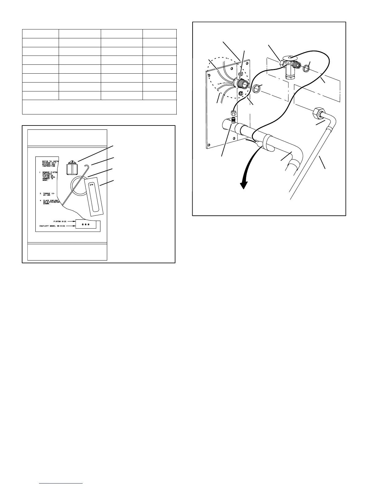
Table 3. Indoor Unit Fixed Orifice Kits
Model Catalog Number Part Number Drill Size
XC14−018 97M74 100484−06 0.053
XC14−024 97M75 100484−08 0.057
XC14−030 97M76 100484−13 0.063
XC14−036 11W02 100484−22 0.073
XC14−042 97M78 100484−24 0.076
XC14−048 11W07 100484−31 0.083
XC14−060 11W11 100484−40 0.093
Use the Lennox catalog number to order a new or replacement fixed
orifice kit.
The fixed orifice kit includes the following components:
FIXED ORIFICE (1)
FIXED ORIFICE
EXTRACTOR (1)
TEFLON RING (1)
FIXED ORIFICE STICKER (1)
Figure 25. Fixed Orifice Kit Components
TYPICAL TXV INSTALLATION PROCEDURE
The TXV unit can be installed internal or external to the
indoor coil. In applications where an uncased coil is being
installed in a field−provided plenum, install the TXV in a
manner that will provide access for field servicing of the
TXV. Refer to Figure 26 for reference during installation of
TXV unit.
To prevent any possibility of water damage, properly
insulate all parts of the TXV assembly that may sweat due
to temperature differences between the valve and its
surrounding ambient temperatures.
TWO PIECE
PATCH PLATE
(UNCASED COIL
ONLY)
SUCTION
LINE
LIQUID LINE
ORIFICE
HOUSING
DISTRIBUTOR
TUBES
LIQUID
LINE
MALE EQUALIZER LINE
FITTING (SEE FIGURE 28
FOR FURTHER DETAILS)
SENSING
LINE
EQUALIZER
LINE
TXV
TEFLON
RING
(Uncased Coil Shown)
SENSING BULB INSULATION IS
REQUIRED IF MOUNTED EXTERNAL
TO THE COIL CASING. SEE FIGURE 27
FOR BULB POSITIONING.
STUB END
TEFLON
RING
LIQUID LINE ASSEMBLY
WITH BRASS NUT
DISTRIBUTOR
ASSEMBLY
Figure 26. Typical TXV Installation
1. Remove the field−provided fitting that temporary
reconnected the liquid line to the indoor unit’s
distributor assembly.
2. Install one of the provided Teflon rings around the
stubbed end of the TXV and lightly lubricate the
connector threads and expose surface of the Teflon
ring with refrigerant oil.
3. Attach the stubbed end of the TXV to the liquid line
orifice housing. Finger tighten and use an appropriately
sized wrench to turn an additional 1/2 turn clockwise
as illustrated in figure 23, or 20 ft−lb.
4. Place the remaining Teflon ring around the other end
of the TXV. Lightly lubricate connector threads and
expose surface of the Teflon ring with refrigerant oil.
5. Attach the liquid line assembly to the TXV. Finger
tighten and use an appropriately sized wrench to turn
an additional 1/2 turn clockwise as illustrated in figure
23, or 20 ft−lb.

 Loading...