Page 19
XC14 SERIES
1. Determine the desired DTMeasure entering air temperature
using dry bulb (A) and wet bulb (B). DT is the intersecting value of A
and B in the table (see triangle).
2. Find temperature drop across coilMeasure the coil’s dry bulb
entering and leaving air temperatures (A and C). Temperature Drop
Formula: (T
Drop
) = A minus C.
3. Determine if fan needs adjustmentIf the difference between the
measured T
Drop
and the desired DT (T
Drop
–DT) is within +3º, no ad-
justment is needed. See examples: Assume DT = 15 and A temp. =
72º, these C temperatures would necessitate stated actions:
Cº T
Drop
– DT = ºF ACTION
53º 19 – 15 = 4 Increase the airflow
58º 14 – 15 = −1 (within +3º range) no change
62º 10 – 15 = −5 Decrease the airflow
4. Adjust the fan speedSee indoor unit instructions to in-
crease/decrease fan speed.
Changing air flow affects all temperatures; recheck temperatures to
confirm that the temperature drop and DT are within +3º.
DT
80 24 24 24 23 23 22 22 22 20 19 18 17 16 15
78 23 23 23 22 22 21 21 20 19 18 17 16 15 14
76 22 22 22 21 21 20 19 19 18 17 16 15 14 13
74 21 21 21 20 19 19 18 17 16 16 15 14 13 12
72 20 20 19 18 17 17 16 15 15 14 13 12 11 10
70 19 19 18 18 17 17 16 15 15 14 13 12 11 10
57 58 59 60 61 62 63 64 65 66 67 68 69 70
Temp.
of air
entering
indoor
coil ºF
INDOOR
COIL
DRY
BULB
DRY
BULB
WET
BULB
B
T
Drop
19º
A
Dry−bulb
Wet−bulb ºF
A
72º
B
64º
C
53º
air flowair flow
All temperatures are
expressed in ºF
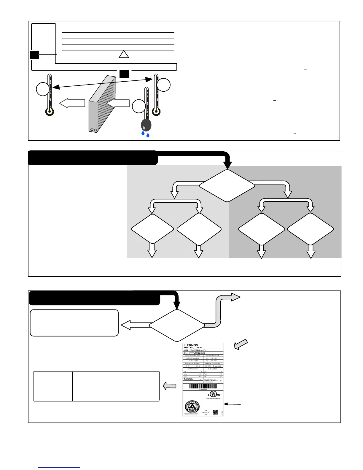
Figure 33. Checking Indoor Airflow over Evaporator Coil using Delta−T Chart
WHEN TO CHARGE?
Warm weather best
Can charge in colder weather
CHARGE METHOD? Determine by:
Metering device type
Outdoor ambient temperature
REQUIREMENTS:
Sufficient heat load in structure
Indoor temperature between 70-80ºF
(21−26ºC)
Manifold gauge set connected to unit
Thermometers:
− to measure outdoor ambient
temperature
− to measure liquid line temperature
− to measure suction line
temperature
TXV
RFC
APPROACH OR
SUBCOOLING
WEIGH-INSUPERHEAT
65ºF
(18.3ºC) and
Above
START: Determine how refrigerant is metered
39ºF
(3.8ºC) and
Below
Which
metering
device?
WEIGH-IN
64ºF
(17.7ºC) and
Below
40ºF
(4.4ºC) and
Above
Figure 34. Determining HFC−410A Charge Method
WEIGH IN TXV
START: Measure outdoor ambient temperature
1. Check Liquid and suction line pressures
2. Compare unit pressures with table 7,
Normal Operating Pressures.
3. Conduct leak check; evacuate as
previously outlined.
4. Weigh in the unit nameplate charge plus
any charge required for line set differences
over feet.
Liquid Line
Set Diameter
Ounces per 5 feet (g per 1.5 m)
adjust from 15 feet (4.6 m) line set*
3/8" (9.5 mm)
3 ounce per 5’ (85 g per 1.5 m)
NOTE − *If line length is greater than 15 ft. (4.6 m), add this
amount. If line length is less than 15 ft. (4.6 m), subtract this
amount.
Refrigerant Charge per Line Set Length
USE EITHER APPROACH
OR SUBCOOLING
METHOD
This nameplate is for illustration purposes
only. Go to actual nameplate on outdoor
unit for charge information.
64ºF and
BELOW
65ºF
and
ABOVE
ABOVE or
BELOW
Figure 35. Using HFC−410A Weigh In TXV Method
 Loading...