Page 21
XC14 SERIES
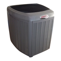
WEIGH IN RFC
START: Measure outdoor ambient temperature
1. Check Liquid and suction line pressures
2. Compare unit pressures with table 7,
Normal Operating Pressures.
3. Conduct leak check; evacuate as
previously outlined.
4. Weigh in the unit nameplate charge plus
any charge required for line set differences
over feet.
Liquid Line
Set Diameter
Ounces per 5 feet (g per 1.5 m)
adjust from 15 feet (4.6 m) line set*
3/8" (9.5 mm)
3 ounce per 5’ (85 g per 1.5 m)
NOTE − *If line length is greater than 15 ft. (4.6 m), add this
amount. If line length is less than 15 ft. (4.6 m), subtract this
amount.
Refrigerant Charge per Line Set Length
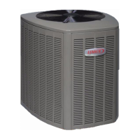
USE SUPERHEAT
This nameplate is for illustration purposes
only. Go to actual nameplate on outdoor unit
for charge information.
ABOVE or
BELOW
39ºF and
BELOW
40ºF
and
ABOVE
Figure 38. Using HFC−410A Weigh In RFC Charge Method
START: Measure outdoor ambient temperature
NOTE − Do not attempt to charge system
where a dash appears, system could be
overcharged. Superheat is taken at
suction line service port. Suction line
superheat must never be less than 5ºF at
the suction line service port.
USE WEIGH-IN METHOD
Weigh-in or remove refrigerant
based upon line length
SHº (Superheat) Values (+/−5ºF)
Wet Bulb (air entering indoor coil)
ºF* 50 52 54 56 58 60 62 64 66 68 70 72 74 76
40 15 18 20 23 26 29 32 34 38 41 43 46 48 51
45 13 16 18 21 24 27 30 33 36 39 41 44 46 49
50 11 14 16 19 22 25 28 31 34 37 39 42 44 47
55 9 12141720232730333638404244
60 7 10121518212427303335384043
65 - 6 10 13 16 19 21 24 27 30 33 36 38 41
70 - - 7 1013161921242730333639
75 - - - 6 9 121518212428313437
80 - - - - 5 8 12 15 18 21 25 28 31 35
85 - - - - - - 8 11 15 19 22 26 30 33
90 - - - - - - 5 9 131620242731
95 - - - - - - - 6 101418222529
100 --------81216212428
105 --------5913172226
110 ---------611152025
115 ----------8141824
* Dry−bulb temperature (ºF) of entering outdoor ambient air.
1. Confirm proper airflow across coil using figure 33.
2. Compare unit pressures with table 7, Normal
Operating Pressures.
3. Use SUPERHEAT to correctly charge unit or to
verify the charge is correct.
4. Set thermostat to call for heat (must have a cooling
load between 70-80ºF (21−26ºC)
5. Connect gauge set.
6. When heat demand is satisfied, set thermostat to
call for cooling.
7. Allow temperatures and pressures to stabilize.
8. Measure the suction line pressure and use the use
value to determine saturation temperature (table
6):
SATº =_________
9. Record suction line temperature:
VAPº =_________
10. Subtract to determine superheat (SHº):
VAPº − _____ SATº ______ = SHº______
11. Record the wet bulb temperature (air entering
indoor coil):
WB =_______
12. Record outdoor ambient temperature.
13. Compare results with table to the left.
If value is MORE
than shown, remove
refrigerant.
If value is LESS than
shown, add
refrigerant.
If refrigerant is
added, retest to
confirm that unit is
properly charged.
MORE or
LESS
If refrigerant is
removed, retest to
confirm that unit is
properly charged.
ABOVE or
BELOW
39ºF and
BELOW
40ºF
and
ABOVE
Figure 39. Using HFC−410A Superheat RFC Charge Method

 Loading...