Page 10
D − Condenser Fan Motor (B4)
All units use single−phase PSC fan motors which require a run
capacitor. In all units, the condenser fan is controlled by
the compressor contactor.
ELECTRICAL DATA tables in this manual show specifi-
cations for condenser fans used in XC16’s.
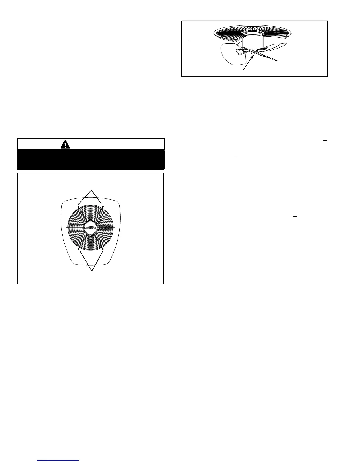
Access to the condenser fan motor on all units is gained
by removing the four screws securing the fan assembly.
See figure 4. The grill fan assembly can be removed from
the cabinet as one piece. See figure 5. The condenser fan
motor is removed from the fan guard by removing the four
nuts found on top of the grill. See figure 5 if condenser fan
motor replacement is necessary.
Make sure all power is disconnected before
beginning electrical service procedures.
DANGER
FIGURE 4
Remove
screws
Remove
screws
ALIGN FAN HUB FLUSH WITH END OF SHAFT
FIGURE 5
E − Low Pressure Switch (S87)
All XC16 units are equipped with an auto-reset, single-pole/
single-throw low pressure switch is located in the vapor line.
This switch shuts off the compressor by de−energizing K1
when vapor line pressure drops below the factory setting.
The switch is closed during normal operating pressure con-
ditions and is permanently adjusted to trip (open) at 40 +
5
psi. The switch automatically resets when vapor line pres-
sure rises above 90 +
5 psi.
F − High Pressure Switch (S4)
XC16 units are equipped with a high pressure switch that is
located in the liquid line of the compressor. The switch
(SPST, manual reset, normally closed) removes power from
the compressor contactor control circuit when discharge
pressure rises above factory setting at 590 +
10 psi.
G − Crankcase Heater (HR1) &
Thermostat (S40) −048 and −060 units only
Compressor in the XC16−048 and −060 units are equipped
with a 70 watt, belly band type crankcase heater. HR1 pre-
vents liquid from accumulating in the compressor. HR1 is
controlled by a thermostat located on the liquid line. When liq-
uid line temperature drops below 50° F the thermostat closes
energizing HR1. The thermostat will open, de−energizing
HR1 once liquid line temperature reaches 70° F .
 Loading...