ngs
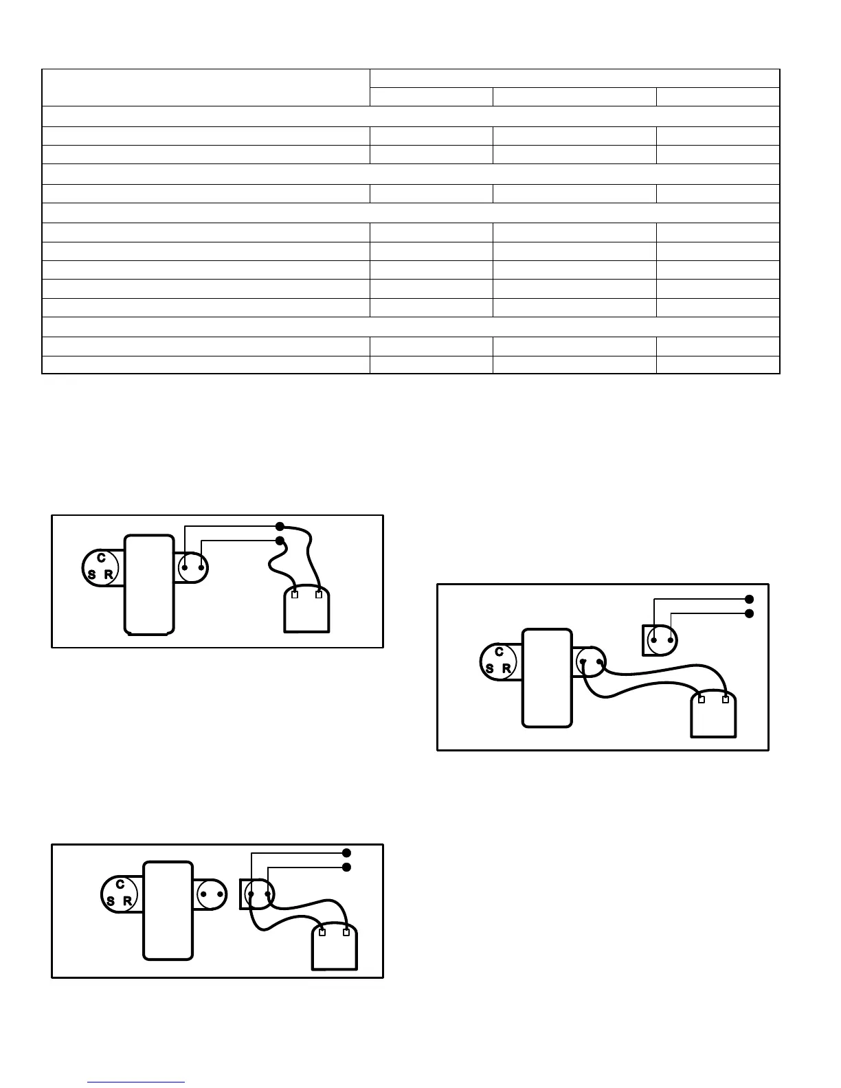
Y1 − 1st-Stage Expected Results Y2 − 2nd-Stage
Compressor
Voltage Same
Amperage Higher
Condenser Fan motor
Amperage Same or Higher
Temperature
Ambient Same
Outdoor Coil Discharge Air Higher
Compressor Discharge Line Higher
Indoor Return Air Same
Indoor Coil Discharge Air Lower
Pressures
Suction (Vapor) Lower
Liquid Higher
STEP 2 Confirm DC voltage output on compressor
solenoid plug
11 − Shut power off to outdoor unit.
12 − Supply 24 volts AC control voltage to the wire ends of
the full wave rectifier plug. Listen for a click" as the sole-
noid is energized. See figure 6.
compressor
solenoid fusite
terminals
compressor
fusite
terminals
meter
rectifier plug leads
apply 24vac
FIGURE 6
13 − Unplug the full wave rectifier plug from the fusite con-
nection on the compressor.
14 − Turn the low voltage power back onto the unit. Supply
24VAC to the wires of the full wave rectifier plug. Set volt
meter to DC volts and measure the DC voltage at the fe-
male connector end of the full wave rectifier plug. The
DC voltage reading should be 1.5 to 3 volts lower than
the input voltage to the plug wire leads. (EX: Input volt-
age is 24VAC output voltage is 22VDC). See figure 7.
meter
rectifier plug leads
compressor
fusite
terminals
solenoid
fusite
terminals
compressor
apply 24vac
FIGURE 7
If the above checks verify that the solenoid plug is provid-
ing power to cycle into high capacity operation, continue
to step 3 to determine if problem is with solenoid coil in
compressor
STEP 3 Confirm internal unloader solenoid has prop-
er resistance
15 − Shut all power off to unit (main and low voltage)
16 − Unplug the molded plug from the compressor solenoid
2−pin fusite.
17 − Using a volt meter set on the 200 ohm scale
meter
rectifier plug leads
compressor
fusite
terminals
solenoid
fusite
terminals
compressor
FIGURE 8
Replace the Compressor under these conditions:
Bad Solenoid
a. Measure the resistance at the 2−pin fusite. See figure 8.
The resistance should be 32 to 60 ohms depending on
compressor temperature. If no resistance replace com-
pressor.
b. Measure the resistance from each fusite pin to ground.
There should not be continuity to ground. If solenoid coil
is grounded, replace compressor.
Good Solenoid
a. Seals not shifting, replace compressor
b. Slider ring not shifting, replace compressor.
 Loading...