EasyManuals Logo

Lennox ZGB Series User Manual

Lennox ZGB Series
55 pages
To Next Page IconTo Next Page
To Previous Page IconTo Previous Page
Page #29 background imageLoading...
Page #29 background image

2-High Pressure Switch S4
The high pressure switch is an automatic reset SPST N.C.
         
the compressor discharge line and wired in series with the
compressor contactor coil.

         
opens and the respective compressor is de-energized


         -
ergized. The CMC1 board monitors the pressure switch

       
in this condition. A pressure switch may open and close
again four times during a current demand cycle without
causing a lockout condition by resetting the count at the

strike lockout can only be reset by one of the following

-Power cycle the controller
-Apply the TEST mode

The low ambient switch is an auto-reset SPST N.O. pres-
sure switch which allows for mechanical cooling operation
at low outdoor temperatures. The switch is located in the
liquid line in the compressor section.
-




       
         -


is de-energized. This intermittent fan operation results in
higher evaporating temperature allowing the system to op-
erate without icing the evaporator coil and losing capacity.
4-Compressor Low Discharge Temperature Limit S3

S3 is a thermostat which opens on temperature drop. It is

5-Compressor High Temperature Limit S5
The compressor thermal protector is located on top of the
    


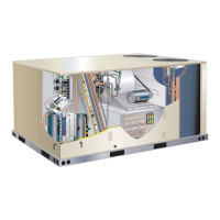
C-Blower Compartment
All units are equipped with belt drive blowers. See unit
nameplate for blower type.
1-Blower Wheels



2-Indoor Blower Motor B3
    
-


        
front of this manual. Units may be equipped with motors
     -


IMPORTANT
hree phase scroll compressors must be phased
sequentially for correct compressor and blower
rotation. Follow “COOLING START-UP” section
of installation instructions to ensure proper
compressor and blower operation.
A-Blower Operation
Initiate blower demand at thermostat according to instruc-
tions provided with thermostat. Unit will cycle on thermo-
stat demand. The following steps apply to applications
using a typical electro-mechanical thermostat.
1 - Blower operation is manually set at the thermostat

blowers will operate continuously.
2 - 
cycle with demand. Blowers and entire unit will be
󰀨
B-Determining Unit CFM
IMPORTANT -     CFM
MUST BE ADJUSTED IN HIGH SPEED. Disconnect fac-
-
nectors are located near the bottom of the control box.
-
          
blower on low during ventilation only demands. See table

TABLE 4
TWO-SPEED BLOWER OPERATION
ZGB074S4T UNITS
Thermostat Blower Speed
 
 High
 High
 High
 
 High
*Factory-installed jack/plug connection.

Questions and Answers:

Question and Answer IconNeed help?

Do you have a question about the Lennox ZGB Series and is the answer not in the manual?

Lennox ZGB Series Specifications

General IconGeneral
BrandLennox
ModelZGB Series
CategoryAir Conditioner
LanguageEnglish

Related product manuals