Page 16
ZH 036, 048, 060
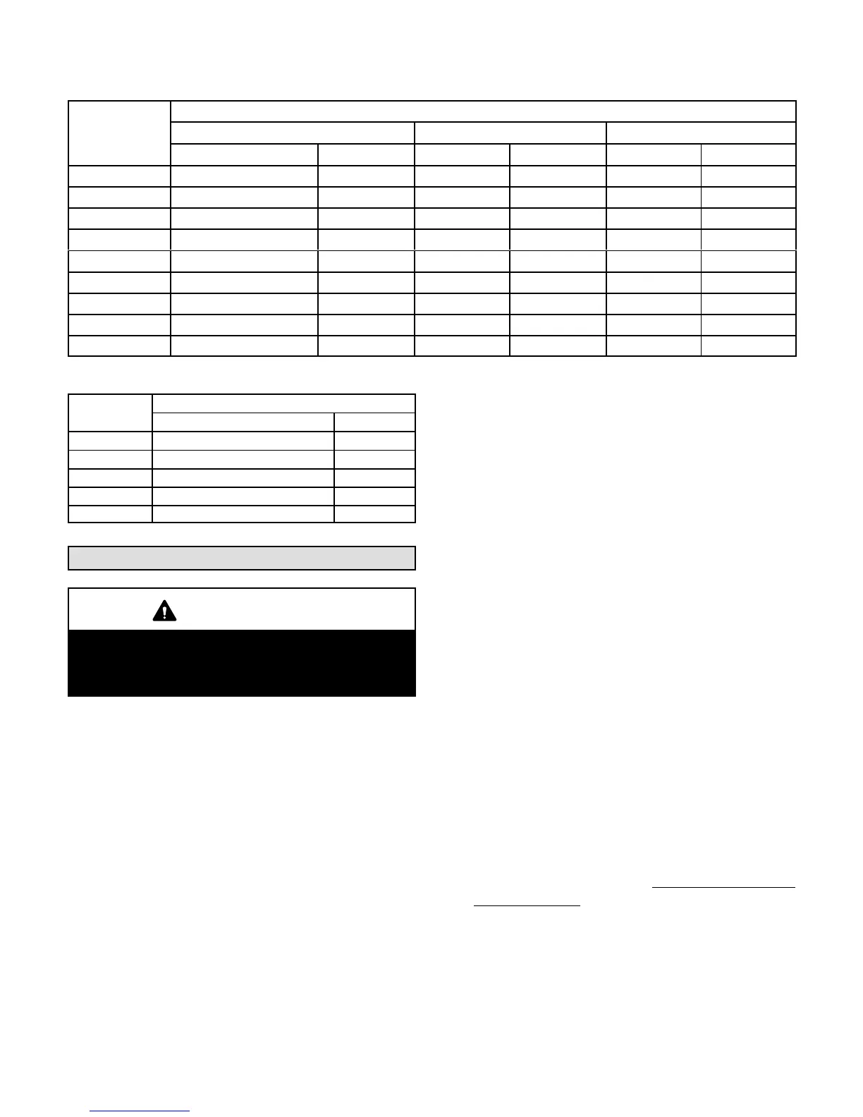
TABLE 2
DRIVE COMPONENT MANUFACTURER'S NUMBERS
Drive No.
DRIVE COMPONENT PART NUMBERS
Motor Pulley Blower Pulley Belts
Browning OEM Browning OEM Browning OEM
Z01 1VP34 X 7/8 31K6901 AK54 X 5/8 10024430 A40 10024517
Z02 1VP34 X 7/8 31K6901 AK46 X 5/8 10024431 A39 10024516
Z03 1VP34 X 7/8 31K6901 AK41 X 5/8 10024428 A39 10024516
Z04 1VP34 X 7/8 31K6901 AK39 X 5/8 10024432 A38 10024515
Z05 1VP44 X 7/8 P81488 AK49 X 5/8 10024426 A41 10024518
Z06 1VP50 X 7/8 53J1501 AK51 X 5/8 10024429 A42 10024519
ZAA01 1VP34 X 7/8 31K69 AK69 X 1 37L47 AX51 13H01
ZAA02 1VP40 X 7/8 79J03 BK80H 100788-03 A53 100245-40
ZAA03 1VP40 X 7/8 79J03 AK59 X 1 31K68 A50 100245-29
TABLE 3
MINIMUM AIRFLOW - UNITS WITH ELECTRIC HEAT
kW
CFM - Downflow and Horizontal
ZHA036-060, ZHB036-048 ZHB060
5 960 1750
7.5 960 1750
10 960 1750
15 960 1750
22.5 1280 1750
Units with electric heat (5-22.5kW) can operate up to 1.6”w.g. maximum static pressure.
Start-Up
IMPORTANT
This unit is equipped with a crankcase heater. Make
sure heater is energized 24 hours before unit start-
up to prevent compressor damage as a result of
slugging.
A-Start-Up
Heating
1- Set thermostat or temperature control device to
initiate a first-stage heating demand.
2- A first-stage heating demand (W1) will energize
compressors 1 and the outdoor fan.
Note - L1 reversing valve is de-energized in the
heating mode.
ZH Units With Optional Electric Heat -
An increased heating demand (W2) will energize
electric heat. Electric heat is also energized during
the defrost cycle (W1) to maintain discharge air
temperature.
Cooling
1- Set thermostat or temperature control device fan
switch to AUTO or ON. Set thermostat or
temperature control device to initiate a first-stage
cooling demand.
A first-stage Y1 cooling demand will energize L1
reversing valve solenoid and compressor 1.
Units With Optional Economizer -
The optional economizer will start on a first stage (Y1)
cooling demand when outdoor air is suitable. An
increased cooling demand (Y2) will energize
compressor 1.
2- Refrigerant circuits are factory charged with R-410A
refrigerant. See unit rating plate for correct amount of
charge.
B-Three Phase Scroll Compressor Voltage Phasing
Three phase scroll compressors must be phased
sequentially to ensure correct compressor and blower
rotation and operation. Compressor and blower are
wired in phase at the factory. Power wires are
color-coded as follows: line 1-red, line 2-yellow, line
3-blue.
1- Observe suction and discharge pressures and
blower rotation on unit start-up.
2- Suction pressure must drop, discharge pressure
must rise, and blower rotation must match rotation
marking.
If pressure differential is not observed or blower rotation is
not correct:
3- Disconnect all remote electrical power supplies.
4- Reverse any two field-installed wires connected to
the line side of K1 contactor. Do not reverse wires at
blower contactor.
Make sure the connections are tight.
Discharge and suction pressures should operate at
their normal start‐up ranges.
 Loading...