Page 5
507111-02 2/2015
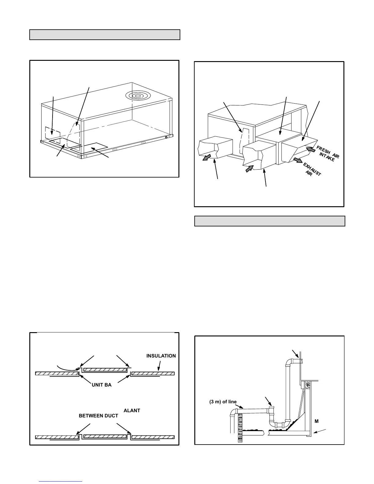
Horizontal Air Discharge
Unit is shipped with panels covering the horizontal supply
and return air openings. See figure 3.
FIGURE 3
DOWNFLOW
RETURN AIR
OPENING
UNIT SUPPLY AND RETURN AIR OPENINGS
DOWNFLOW
SUPPLY AIR
OPENING
HORIZONTAL
RETURN AIR
OPENING
HORIZONTAL
SUPPLY AIR
OPENING
1- Remove horizontal covers and place a bead of silicone
sealant on the underside of the duct cover flanges. See
figure 4.
2- Position covers over downflow openings. Secure
covers with self-drilling screws in at least two places on
each cover. Drill through duct cover side into flange of
base pan.
3- Place a bead of silicone between insulation and duct
cover to seal in insulation edges. Let silicone dry before
running gas or electric heat.
Units Equipped With An Optional Horizontal Economizer
1- Install the horizontal supply air cover over the down
flow supply air opening as described above.
2- Leave the horizontal return air cover in place.
3- Locate the extra horizontal return cover that is
included with the horizontal economizer kit. Install as
described in previous section.
FIGURE 4
INSTALL DUCT COVERS - SIDE VIEW
INSULATION
UNIT BASE
FLANGES
DUCT COVER
FLANGES
APPLY SILICONE
SEALANT TO
FLANGES
APPLY SILICONE SEALANT
BETWEEN DUCT COVER
FLANGE AND UNIT INSULATION
NOT TO
SCALE
4- Install return air duct on the intake air side of the
horizontal economizer. See figure 5.
5- Horizontal economizer and return air duct must be
field-supported.
This opening not used
in horizontal applica
tions with economizer
HORIZONTAL
RETURN AIR DUCT
(FIELD-PROVIDED)
UNIT
HORIZONTAL
SUPPLY AIR DUCT
(FIELD-PROVIDED)
OPTIONAL
HORIZONTAL
ECONOMIZER
HOOD
PROVIDED
WITH
ECONOMIZER
FIGURE 5
HORIZONTAL RETURN AIR DUCTWORK
WITH ECONOMIZER
Condensate Drains
Make drain connection to the drain coupling provided
on unit.
Note - The drain pan is made with a glass reinforced
engineered plastic capable of withstanding typical joint
torque but can be damaged with excessive force. Tighten
pipe nipple hand tight and turn an additional quarter turn.
A trap must be installed between drain connection and an
open vent for proper condensate removal. See figure 6. It is
sometimes acceptable to drain condensate onto the roof or
grade; however, a tee should be fitted to the trap to direct
condensate downward. The condensate line must be
vented. Check local codes concerning condensate disposal.
Refer to pages 1 and 2 for condensate drain location.
FIGURE 6
UNIT
Minimum Pitch
1” (25 mm) per
10' (3 m) of line
MOUNTING
FRAME
OPEN VENT
CONDENSATE SIDE DRAIN CONNECTION
NOTE - Allow clearance to
open doors when installing
condensate piping.
CAULK AROUND CONDENSATE COUPLING
 Loading...