Do you have a question about the Lenovo T24i-30 and is the answer not in the manual?
The provided document is a simplified service manual for dismantling the Lenovo T24i-30 monitor, published by Foxconn Technology Group. This manual outlines the necessary steps and tools for disassembling the monitor, primarily for service, repair, or component replacement.
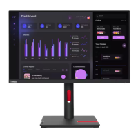
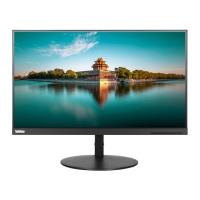
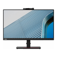
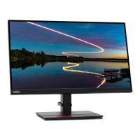
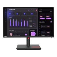
The Lenovo T24i-30 is an LCD monitor designed for display purposes. As a display device, its primary function is to present visual information from a connected computer or other video source to the user. While the manual focuses on its internal components and disassembly, the underlying function is to provide a high-quality visual interface for various computing tasks. The monitor likely features a standard set of input ports to connect to different devices, allowing it to serve as a versatile display solution in office or home environments. Its design suggests a focus on user experience, potentially incorporating features that enhance viewing comfort and productivity, though these are not explicitly detailed in the dismantling guide.
From the perspective of a service manual, "usage features" refer more to the characteristics that impact its serviceability rather than end-user operation. The Lenovo T24i-30 monitor is designed with a structure that allows for systematic disassembly, indicating a modular approach to its internal components. This design facilitates the replacement of individual parts, which is a key feature for extending the product's lifespan and reducing electronic waste.
The manual highlights the importance of proper handling during disassembly, such as placing the monitor on a soft cloth and sponge to prevent damage to the LCD panel. This suggests that while robust for daily use, the internal components, particularly the display panel, are delicate and require careful attention during maintenance. The use of standard tools like Phillips and spacer screwdrivers, along with a C/D disassembly tool, implies that the monitor's construction is accessible to trained technicians with common equipment, rather than requiring highly specialized proprietary tools.
The sequential steps for removing various components—from the rear cover and screws to internal cables (light bar, LVDS, keyboard lines), the middle frame, keypad PCB, mylar sheets, and finally the main PCB and power PCB—illustrate a logical and structured assembly. This modularity is a significant usage feature from a service standpoint, as it allows for targeted repairs. For instance, if the backlight fails, the light bar line can be unplugged and the component replaced without necessarily disturbing other major systems. Similarly, issues with the control buttons can be addressed by accessing the keypad PCB.
The presence of thermal pads on the power PCB indicates a design consideration for heat management, which is crucial for the longevity and stable operation of electronic components. This implies that the monitor is engineered to dissipate heat effectively, a feature that indirectly benefits the end-user by ensuring reliable performance over time.
The Lenovo T24i-30 is designed with several features that streamline maintenance and repair processes. The "Simplified service manual for dismantling" itself is a primary maintenance feature, providing clear, step-by-step instructions with visual aids to guide technicians through the disassembly process. This reduces the learning curve and potential for error during servicing.
Precautionary Measures: The manual emphasizes critical precautions, such as ensuring all power connectors are removed and the monitor is in an off state before beginning any work. This is a fundamental safety and maintenance feature, protecting both the technician and the device from electrical damage. The instruction to handle the LCD carefully and avoid touching or pressing the panel directly highlights the fragility of the display component, guiding technicians to prevent accidental damage during repair.
Tooling Requirements: The specification of appropriate tools (Phillips screwdriver, spacer screwdriver, C/D disassembly tool, gloves/soft cloth) simplifies the preparation for maintenance. This ensures that technicians use the correct tools, minimizing the risk of stripping screws, damaging plastic housings, or leaving fingerprints on sensitive components. The C/D disassembly tool, specifically mentioned for releasing the rear cover hook, indicates a design that uses clips or latches in addition to screws, requiring a specific technique for non-destructive opening.
Modular Disassembly: The sequential removal of components is a core maintenance feature.
Overall, the manual outlines a maintenance process that is structured, tool-specific, and focused on component-level repair, thereby supporting the longevity and serviceability of the Lenovo T24i-30 monitor.
| Display Size | 23.8 inches |
|---|---|
| Resolution | 1920 x 1080 |
| Panel Type | IPS |
| Refresh Rate | 60 Hz |
| Aspect Ratio | 16:9 |
| Brightness | 250 cd/m² |
| Contrast Ratio | 1000:1 |
| Viewing Angle | 178°/178° |
| Color Gamut | 72% NTSC |
| VESA Mount | 100 x 100 mm |
| Power Consumption | 18W (typical) |
| Response Time | 4 ms (Extreme mode) |
| Ports | HDMI, VGA, DisplayPort |
| Stand | Tilt |