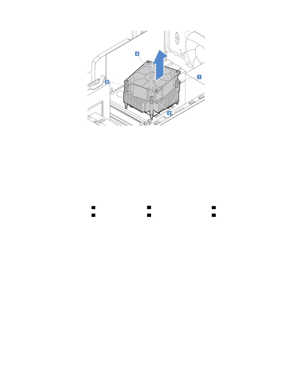
Figure 86. Removing the heat sink and fan assembly
Notes:
• Carefully remove the four screws to avoid any possible damage to the system board. The four screws
cannot be removed from the heat sink and fan assembly.
• Do not touch the thermal grease while handling the heat sink and fan assembly.
6. Align the four screws on the new heat sink and fan assembly with the corresponding screw holes in the
system board. Properly place the heat sink and fan assembly so that you can easily connect its cable to
the CPU fan connector on the system board.
7. Follow the following sequence to install the four screws to secure the new heat sink and fan assembly.
Do not over-tighten the screws.
a. Partially tighten screw
1 , then fully tighten screw 2 , and then fully tighten screw 1 .
b. Partially tighten screw
3 , then fully tighten screw 4 , and then fully tighten screw 3 .
90
ThinkServer TS150 User Guide and Hardware Maintenance Manual