Table 9. Components on the front of the server
Callout Callout
1 LCD diagnostics panel assembly 2 LCD diagnostics panel
3 USB 3.1 Gen 1 (5Gbps) connector 4 External LCD connector
5 XClarity Controller USB connector 6 VGA connector (optional)
7 Rack latch (right)
8 Pull-out information tab
9 Drive bays (16) 10 Rack latch (left)
Note: For more information about each component, see
“Front components overview” on page 22.
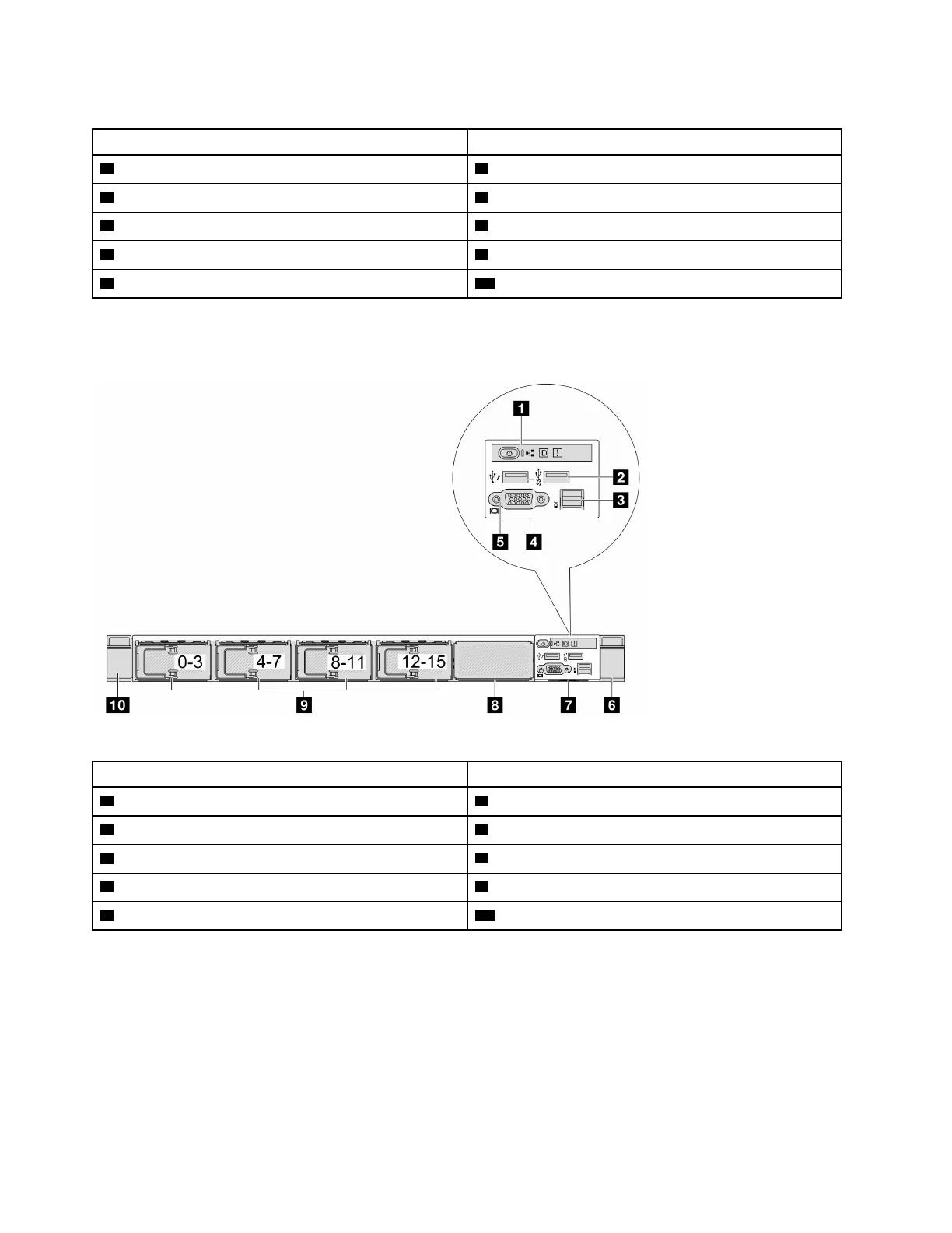
Server model with 16 EDSFF drives and an M.2 cage
Table 10. Components on the front of the server
Callout Callout
1 Diagnostics panel
2 USB 3.1 Gen 1 (5Gbps) connector
3 External LCD connector 4 XClarity Controller USB connector
5 VGA connector (optional) 6 Rack latch (right)
7 Pull-out information tab
8 M.2 cage
9 Drive bays (16) 10 Rack latch (left)
Note: For more information about each component, see “Front components overview” on page 22.
Front components overview
Integrated diagnostics panel
The diagnostics panel is integrated in front I/O module on some models. For information about the controls
and status LEDs on the diagnostics panel, see “Integrated diagnostics panel” in User Guide or Hardware
Maintenance Guide.
22
ThinkSystem SR635 V3 System Configuration Guide

 Loading...


