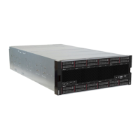
Table 2. Components on the front view (continued)
8 Drive bays 4-7 22 External diagnostics handset connector
9 PCIe slot P3 23 UPI module (Primary chassis)
10 NMI button
24 Sideband card (Primary chassis)
11 Pull-out information tab
25 PCIe slot P2
12 System error LED (yellow) 26 PCIe slot P1
13 System ID button/LED (blue)
27 Drive bays 0-3
14 Network activity LED (green)
1 / 7 / 8 / 27 Drive bays
Install drives to these bays. See “Install a hot-swap drive” in ThinkSystem SR950 V3 User Guide or
ThinkSystem SR950 V3 Hardware Maintenance Guide.
Figure 3. 2.5-inch drive bay numbering Figure 4. E3.S drive bay numbering
2 / 3 / 6 PCIe slots S1-S3
Install PCIe adapters into these PCIe slots. See “Install a PCIe adapter” in ThinkSystem SR950 V3 User
Guide or ThinkSystem SR950 V3 Hardware Maintenance Guide.
4 / 24 Sideband card
Connect the external sideband cables to these sideband cards.
5 / 23 UPI module
Connect the external UPI cables to these UPI modules.
9 / 25 / 26 PCIe slots P1-P3
Install PCIe adapters into these PCIe slots.
10 NMI button
Press this button to force a nonmaskable interrupt to the processor. You might have to use a pen or the end
of a straightened paper clip to press the button. You can also use it to force a blue-screen memory dump.
Use this button only when you are directed to do so by Lenovo Support.
14
ThinkSystem SR950 V3 System Configuration Guide

 Loading...


