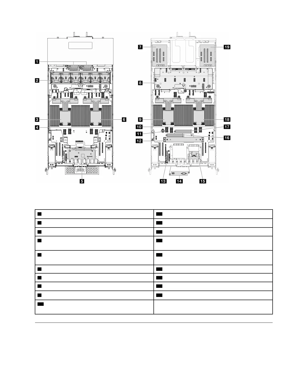
Figure 8. Server top view
Table 4. Component identification (Top view)
1 Power interposer boards (PIB) 11 CMOS battery
2 Fan and fan cage assembly
12 Support bracket
3 CPU7/CPU6 13 Sideband card
4 Memory modules A1-T2 (Upper processor board (CPU
BD))
14 Serial port assembly (Primary chassis only)
5 System I/O board and interposer assembly (Primary
chassis only)
15 Front operator panel and front operator panel cage
(Primary chassis only)
6 CPU5/CPU4
16 M.2 slot 1
7 Left riser card
17 M.2 slot 2
8 Power distribution board (PDB) 18 CPU0/CPU1
9 CPU2/CPU3
19 Right riser card
10 Memory modules A1-T2 (Lower processor board
(MB))
Upper processor board (CPU BD) connectors
The following illustrations show the internal connectors on the upper processor board (CPU BD).
Chapter 2. Server components 19
 Loading...


