16 SF01U
It is not recommended to install contactors or disconnect switches between the drive and motor.
Operating such devices while the drive is running can potentially cause damage to the drive's
power components. If such a device is required, it should only be operated when the drive is
in a STOP state. If there is potential for the device to be opened while the drive is running, the
drive must be programmed for COAST to stop (see Parameter 4 - STOP METHOD), and an
auxiliary contact on the device must be interlocked with the drive's run circuit. This will give
the drive a stop command at the same time the device opens, and will not allow the drive to
start again until the device is closed.
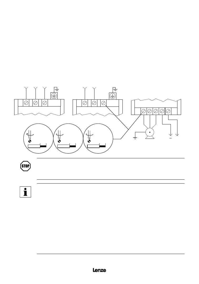
9.0 SCF POWER WIRING DIAGRAM
3 PHASE
AC MOTOR
DC BUS
VOLTAGE
OUTPUT (ALL SERIES)
T1 T2 T3 B- B+
+
SINGLE PHASE INPUT
(SF200Y SERIES)
L1 L2 L3
THREE PHASE INPUT
(SF200, SF200Y, SF400,
AND SF500 SERIES)
L1 L2 L3
4.5 lb-in / 0.5 Nm
0.24 in / 6 mm
10 lb-in / 1.2 Nm
0.35 in / 9 mm
18 lb-in / 2.0 Nm
0.5 in / 13 mm
15 - 30 HP
(11 - 22 kW)
7.5 - 10 HP
(5.5 - 7.5 kW)
0.25 - 5 HP
(0.37 - 3.7 kW)
STOP!
DO NOT connect incoming AC power to output terminals T1, T2, T3, or
terminals B+, B-! Severe damage to the drive will result.
NOTE
• WIRE AND GROUND IN ACCORDANCE WITH NEC OR CEC, AND ALL
APPLICABLE LOCAL CODES.
• Motor wires MUST be run in a separate steel conduit away from control
wiring and incoming AC power wiring.
• Do not install contactors between the drive and the motor without consulting
AC Technology for more information. Failure to do so may result in drive
damage.
• Use only UL and CSA listed and approved wire.
• Minimum wire voltage rating is 300 V for 120, 208, and 240 Vac systems,
and 600 V for 400 and 480 Vac systems.
• Wire gauge must be based on a minimum of 125% of the rated input/output
current of the drive, and a minimum 75°C insulation rating. Use copper
wire only.
Artisan Technology Group - Quality Instrumentation ... Guaranteed | (888) 88-SOURCE | www.artisantg.com
 Loading...