56 SF01U
APPENDIX B - PI SETPOINT CONTROL OPTION
The following describes the PI Setpoint Control software option for the SCF drive. This software
option has additional parameters compared to the standard SCF drive. Also, some of the
parameters found in the standard drive have changed in the PI version.
PI Setpoint Control allows the SCF drive to maintain a process setpoint, such as PSI or CFM,
without using an external controller. When PI is activated the SCF will operate in a closed-loop
fashion, automatically adjusting the motor speed to maintain the process setpoint.
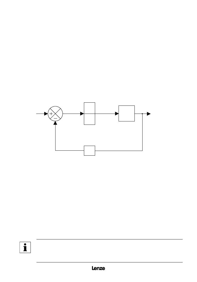
PI setpoint control requires feedback from the process in order to compare the actual process
value to the setpoint. The difference between this value and the setpoint is called the error.
The SCF drive will increase or decrease the motor speed in an attempt to minimize the error.
By constantly adjusting the motor speed, the PI control will drive the process toward the
setpoint. Refer to the PI block diagram below:
B.1 DIRECT ACTING vs. REVERSE ACTING SYSTEMS
The PI function must be set to match the type of system that it will control. A direct (or normal)
acting system requires an increase in motor speed if the process variable decreases. A reverse
acting system requires a decrease in motor speed if the process variable decreases. Parameter
61 - PI MODE must be programmed to the setting that matches the system (normal or reverse
acting) and also the type of feedback signal that is used (0-10 VDC or 4-20 mA).
B.2 FEEDBACK DEVICES
A transducer or transmitter is required to monitor the process variable and provide feedback
to the PI unit in order to compare the process value with the desired setpoint. A transducer
outputs a signal corresponding to a fixed range of the process variable. A transmitter provides
offset and gain adjustments to allow the output signal to be adjusted to correspond to different
ranges of the process variable. Typical output signals for transducers and transmitters are
0-10 VDC or 4-20 mA.
NOTE
If a 4-20 mA signal is used for feedback, and the signal is lost, the drive
will display "FL" to indicate the lost signal. The signal is considered lost if it
drops below 2 mA.
SETPOINT
PROCESS
VARIABLE
(PSI, CFM, etc)
Process Variable
Feedback
Motor
Error
Speed
Command
P
I
Artisan Technology Group - Quality Instrumentation ... Guaranteed | (888) 88-SOURCE | www.artisantg.com
 Loading...