Do you have a question about the Lenze 633 and is the answer not in the manual?
Detailed technical specifications including power, voltage, current, and dimensions.
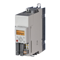
Overview of the inverter's power stage and control module.
Functional description of the mains input and DC bus stages.
Description of the control module and its monitoring functions.
Detailed breakdown of signal inputs and outputs for the control module.
Description of internal circuits like voltage regulators and signal processors.
Diagram of the main power switching module.
Diagram showing terminal connections for the control module.
Diagram showing terminal connections for the power stage.
Details on how different modules are interconnected.
Step-by-step guide for troubleshooting when the motor fails to start.
Procedures for checking mains voltage and fuse integrity.
Tests for key power stage components like rectifier, capacitors, and relay.
Troubleshooting steps when the unit trips during operation.
Addressing issues related to overheating and overcurrent.
Verifying control signals and physical connections.
Procedure for measuring the mains rectifier with an ohmmeter.
Resistance checks for inverter components using an ohmmeter.
| Protection Class | IP20 |
|---|---|
| Enclosure Rating | IP20 |
| Control Mode | vector control |
| Communication Interfaces | CANopen, PROFIBUS, Ethernet |
| Protection Features | Overcurrent, overvoltage, undervoltage, overtemperature |