Electrical installation
HighLine C control terminals
Digital inputs and outputs
6
l
226
EDS84ASC552 EN 8.1
Example circuit
) Note!
For stable digital output states, in particular during the starting phase of the
controller, you must use an external 24V supply for the digital outputs.
) Note!
Digital inputs and digital outputs have separated reference potentials (GI and
GO). If you interconnect inputs and outputs, the reference potentials are
connected as well by an external bridge.
0 1
DC 24 V
(+19.2...+28.8 V)
S1
24 V int.
50 mA
24EDI1DI2
DI3
DI4
RFR
2.7k
2.7k
3.3k
3.3k
3.3k
X5
GND-I
DI5
DI6
DI7
GI
24I
1.6k
1.6k
3.3k
E84AVHC...
24O
DC 24 V
(+19.2...+28.8 V)
X4 DO1DO2
DO3
GO
GND-O
E84AVHC...
8400HLC045 8400HLC045
2
24 V int.
50 mA
24E
DI1
DI2
DI3
DI4
RFR
DC 24 V
(+19.2...+28.8 V)
S1
3.3k
2.7k
2.7k
3.3k
X5
GND-I
DI5
DI6
DI7
GI 24I
3.3k
1.6k
1.6k
3.3k
"
E84AVHC...
8400xLC022
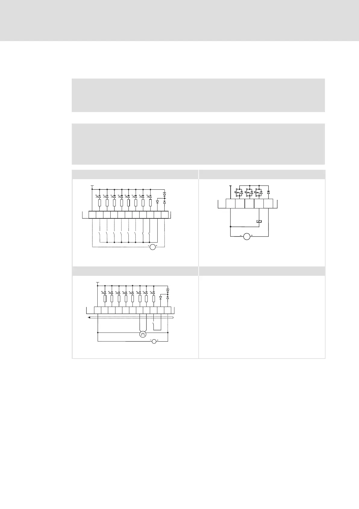
Fig. 6−42 Wiring examples of the digital inputs and outputs
0 Wiring with one (or several) digital input (here: DI1), e.g. a PLC; optional: external
24 V supply
1 Digital control (relay, valve, ...) with external 24 V supply
2 Connection of an HTL incremental encoder with a maximum input frequency of
200 kHz
DI1 track A
DI2 track B
X4 Terminal for the digital outputs
X5 Terminal for the digital inputs
GI GND−I Ground reference potential for the digital inputs
GO GND−O Ground reference potential for the digital outputs
Buy: www.ValinOnline.com | Phone 844-385-3099 | Email: CustomerService@valin.com

 Loading...