Installation
820XBA1097 4-15
Lx
U
V
W
M
3~
PE
RB1 RB2+UG
-UG
RB
Netz
PE
82XX
K10
Z3
Z2
PE
PE
Z1
PE
n
PE
789
GND 1
GND 2
PE
Vref
Vcc
-UG
+UG
F1
-X1
n
n
n
n
K1
62
K11
K12 K14
20
28
E1
E2
E3
E4 39
PES
PES
PES
PES PES
PES
PES
PES
PES
PE
PE
n
n
PES
PES
K35.0082
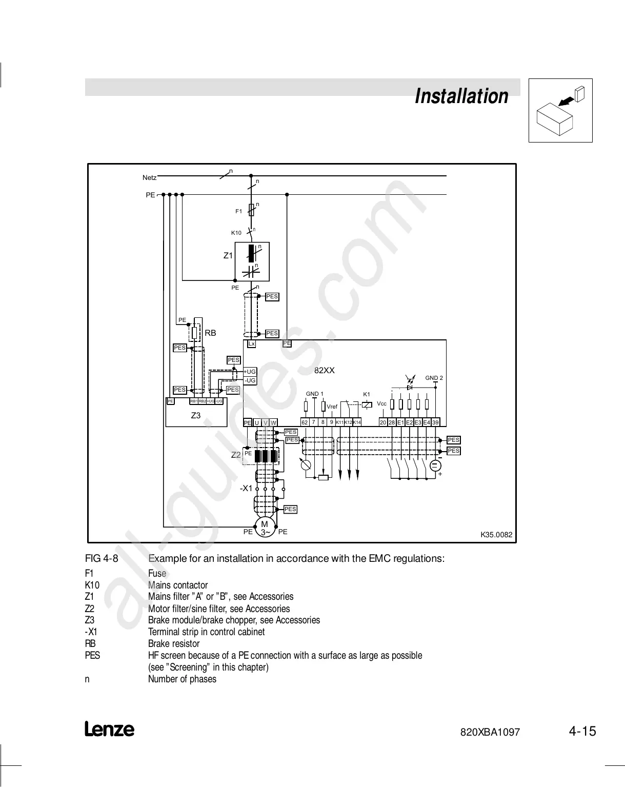
FIG 4-8 Example for an installation in accordance with the EMC regulations:
F1 Fuse
K10 Mains contactor
Z1 Mains filter ”A” or ”B”, see Accessories
Z2 Motor filter/sine filter, see Accessories
Z3 Brake module/brake chopper, see Accessories
-X1 Terminal strip in control cabinet
RB Brake resistor
PES HF screen because of a PEconnection with a surface as large as possible
(see ”Screening” in this chapter)
n Number of phases