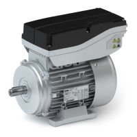
Motor connecon
Connecon via terminal box
Observe the notes on wiring, data on the nameplate, and the connecon diagram in the
terminal box.
The connecon must ensure a connuous and safe electrical supply:
•
No protruding wire ends
•
Use assigned cable end ngs
•
Ensure good electrical conducvity of the contact (remove paint residues) if an addional
PE connecon is used
•
Establish a safe protecve earth connecon
•
Aer the connecon is completed, make sure that all connecons on the terminal board
are rmly ghtened
•
The terminal box has to be free of foreign bodies, dirt, and humidity
•
All unused cable entries and the terminal box itself must be sealed so that they are dust-
ght and waterproof
The smallest air gaps between uncoated, live parts and against earth must not fall below the
following values:
Minimum requirements for basic insulaon
according to IEC/EN 60664-1 (CE)
Higher requirements for UL design Motor diameter
3.87 mm 6.4 mm <178 mm
9.5 mm > 178 mm
Cable glands
The bore holes for the cable glands M25, M20 and M32 are located on both
sides and closed. They can be opened according to need.
Motor MCS09 MCS14L15 MCS14L32
MCS12 MCS14P14 MCS14P32
MCS14H MCS19F15 MCS19F13
MCS19J15 MCS19J30
MCS19P
Screwed connecons 2x M20
2x M25
2x M32
cable cross-secon
mm
2
0.08 ... 2.5
4 (without wire end ferrule)
0.2 ... 10
Stripping length mm 10 ... 11
Terminal design Spring-loaded terminal
Electrical installaon
Motor connecon
Connecon via terminal box
22