Installation and maintenance
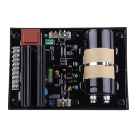
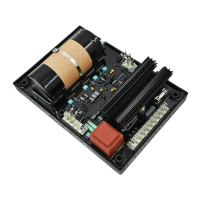
R448 & R448 V50
A.V.R.
3972 en - 02.2008 / d
LEROY-SOMER
11
4 - INSTALLATION - COMMISSIONING
4.1 - Electrical checks on the AVR
- Check that all connections have been
made properly as shown in the attached
wiring diagram.
- Check that the ST3 frequency selection
jumper is on the correct frequency setting.
- Check whether the ST4 jumper or the
remote adjustment potentiometer have
been connected.
- Optional operating modes.
• ST1 jumper : open to connect the R 731
or R 734 3-phase
sensing module.
• ST2 jumper : open if rapid response time
used
• ST5 jumper : open to suppress the LAM
function.
• ST9 jumper : closed with AREP, open
with PMG.
4.2 - Settings
The machine is tested and set at the
factory. When first used with no load,
make sure that the drive speed is
correct and stable (see the nameplate).
After operational testing, replace all
access panels or covers.
The only possible adjustments to the
machine should be made on the AVR.
4.2.1 - R448 settings (AREP or PMG
system)
Before any intervention on the A.V.R.,
make sure that the ST9 jumper is closed
with AREP / SHUNT excitation and
disconnected with PMG or separate
excitation.
a) Initial potentiometer settings (see table
below)
- Remote voltage adjustment potentiometer
: centre (ST4 jumper removed).
Stability adjustments in standalone
operation
b) Install a D.C. analogue voltmeter (needle
dial) cal. 100V on terminals E+, E- and an
A.C. voltmeter cal 300 - 500 or 1000V on the
alternator output terminals.
c) Make sure that the ST3 jumper is
positioned on the desired frequency (50 or
60 Hz).
d) Voltage potentiometer P2 at minimum,
fully anti-clockwise.
e) Stability potentiometer P3 to around 1/3 of
the anti-clockwise limit.
f) Start the engine and set its speed to a
frequency of 48 Hz for 50 Hz, or 58 for 60
Hz.
g) Set the output voltage to the desired
value using P2.
- Rated voltage UN for solo operation (eg.
400 V)
- Or UN + 2 to 4% for parallel operation with
C.T. (eg. 410 V)
If the voltage oscillates, use P3 to make
adjustments (try both directions) observing
WARNING
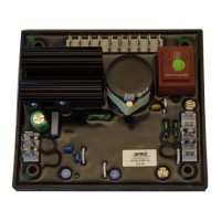
P2
P3
P1
P5
10 A
maximum
400V - 50 Hz
(Input
0 - 380 V)
Not set
(centre position)
Not set
(fully anti-
clockwise)
Excitation ceiling
Limit of excitation and
short-circuit current,
minimum fully anti-clockwise.
Voltage quadrature droop
(// operation with C.T.)
- 0 quadrature loop fully
anti-clockwise.
Voltage
minimum fully anti-clockwise
Stability
Action
Factory setting
Pot.
 Loading...