Electrical connection
Leuze electronic GmbH + Co. KG MSI-SR4B 14
Table 7.1: Terminal assignments
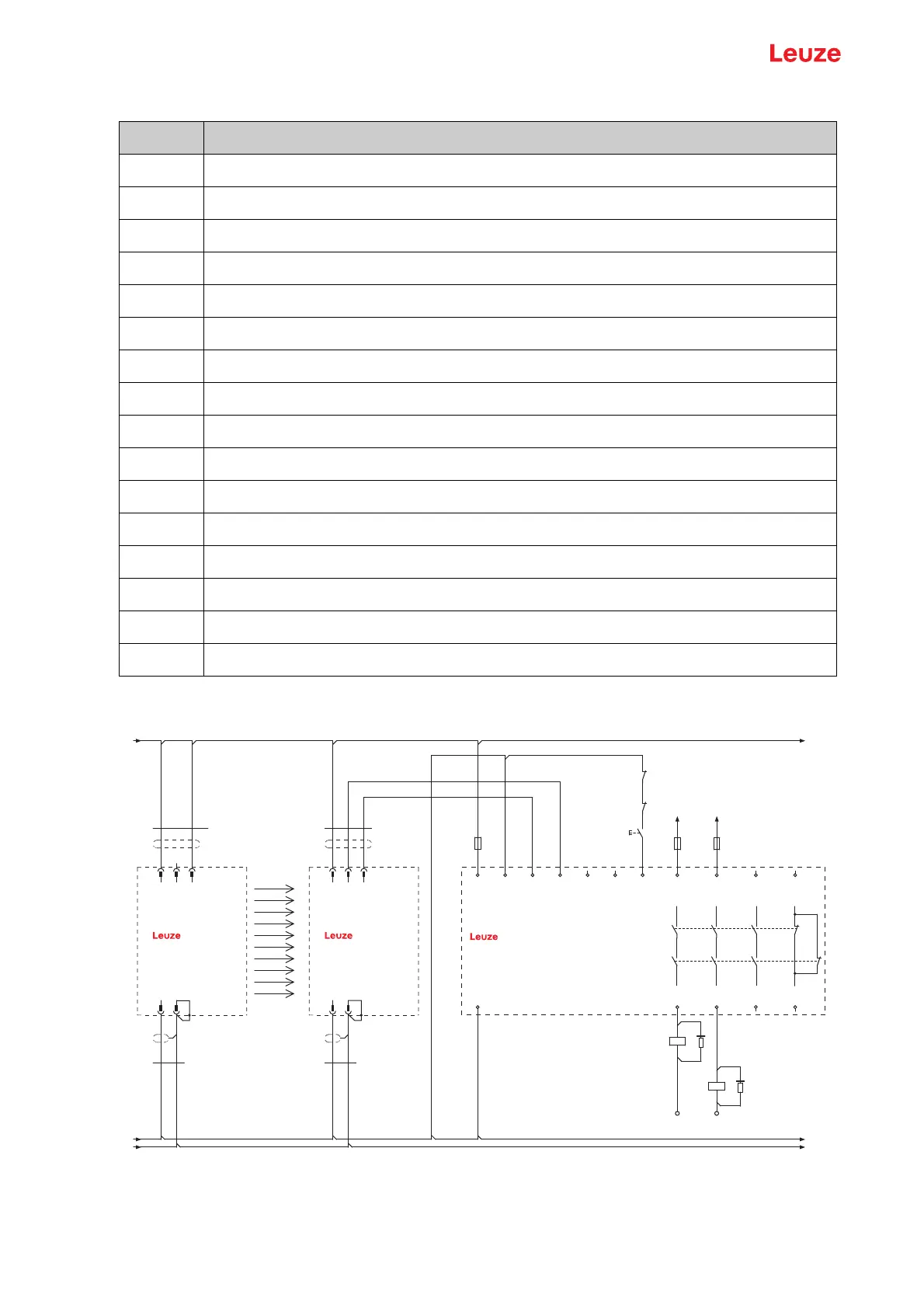
7.2 Circuit diagram examples
Figure 7.1: MSI-SR4B with MLC 510 safety light curtain
Terminal MSI-SR4B
13 Relay contact 1 IN
23 Relay contact 2 IN
33 Relay contact 3 IN
41 Signal contact IN
A1 +24V
S35 Restart input
S33 Sensor supply, contacts 24V OUT
S22 Sensor input
S12 Sensor input
A2 0V
S34 Restart automatic output
S31 Sensor input
14 Relay contact 1 OUT
24 Relay contact 2 OUT
34 Relay contact 3 OUT
42 Signal contact IN
MLCx10R
VIN1
VIN1
RNG
OSSD2
MLCx00T
OSSD1
VIN2
FE/Shield
FE/Shield
VIN2
4
BN
BK
WH
-A1
1 2
3
4
-A2
1 2
3
BN
BK
-W1
-W2
5
-W2
GY
BU
-W1
5
GY
BU
0V
PE
+24V
PE
+24V
0V
n.c.
14 24 42
13 23 41
A1
A2
-K3
1
2
1
2
L+ L+
L- L-
-S1
-K3
-K4
+24V
0V
MSI-SR4B
A1
-A3
A2
S22 S12 S31 S33 S34 S35
2 AOPD-
1 AOPD+
33
34
A1
A2
-K4
2 AOPD+
IV-0
RES-0
RES-I
1
2
*
*


 To Next Page