Hardware Manual
11
Press and hold the orange tab as you insert the wire through the pin slot, then release the orange
tab to secure the wire.
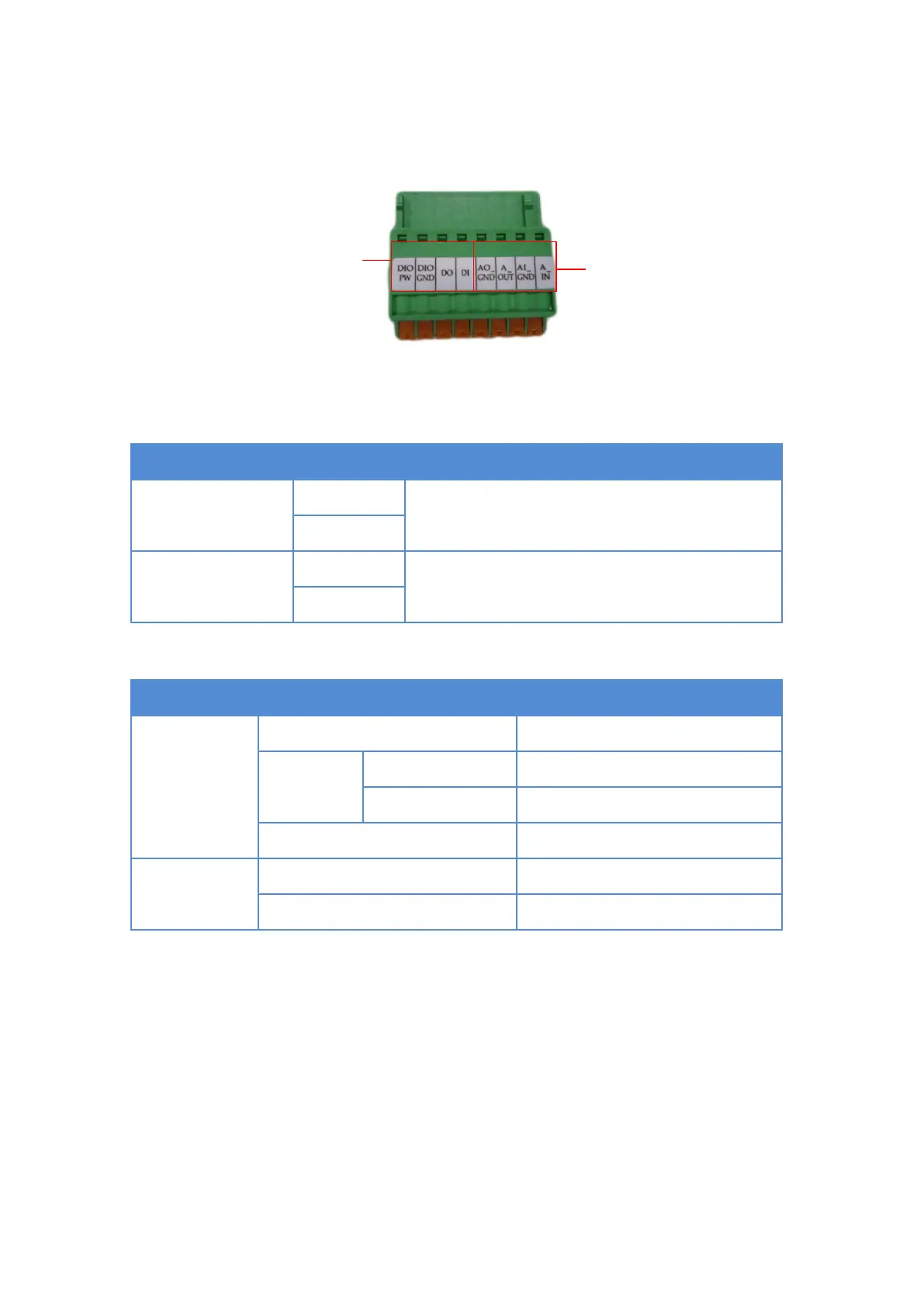
To connect digital input / output devices (DI/DO), map the pins to one of the pin combinations
below:
Connect the wires of the output device to DIO PW
and DO.
Connect the wires of the input device to DIO GND
and DI.
The table below shows the DI/DO connection specifications:
TTL - compatible logic levels
Logic level 1: 3.1V ~ 30V
Transistor (Open Collector)