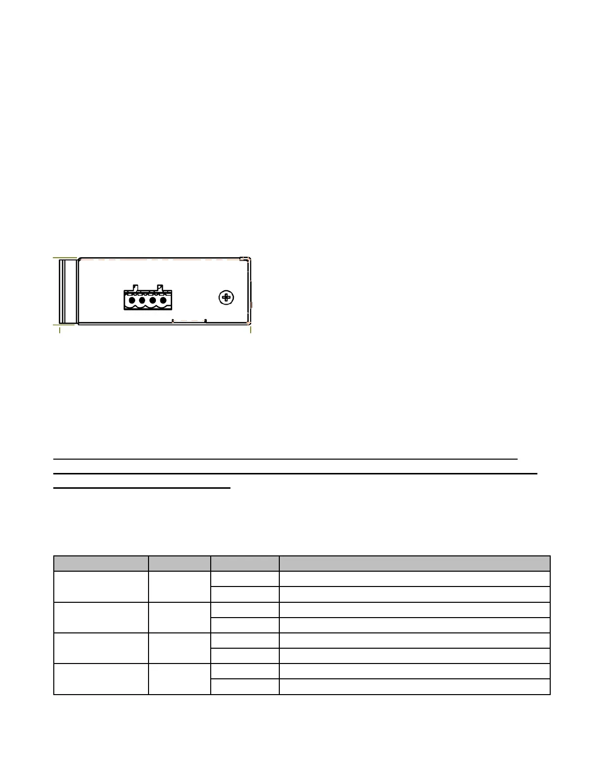
Power connection
This unit provides 4 pin terminal block. It can be operated using 48-56VDC power
source. Always Make sure your input voltage is within this supported voltage
range. You need to use 56VDC input to generate IEEE802.3at 30Watts power.
To make power connection – Follow the printed polarity for V+, V- and RLY.
Connect positive wire to V+, connect negative wire to V- and also connect neutral
wire to ground.
+V- is for power input connection, this unit has only one power input.
RLY is for relay connection.
Connecting procedure:
STEP 1 –
Take out 4 pin terminal block located in the included mounting kit package.
STEP 2 –
Connect power wire to +V- with correct polarity. Connect RLY for relay.
STEP 3 –
Plug into terminal block socket shown above. Polarity needs to match the V+ and V-
WARNING -- Always SHUTS OFF power source to connect power wire.
WARNING -- Any exceeded input voltage will not make this unit function
and may damage this unit.
LED indicator