16 Series Taper Nose In-Line Detachable Connectors
Rated: 600V, up to 400A continuous current using 4/0 cable with 90° C insulation
Cable Size: #2 - 4/0
18 Series Ball Nose In-Line Detachable Connectors
Rated: 600V, up to 400A continuous current using 4/0 cable with 90° C insulation
Cable Size: #2 - 4/0
FEATURES
Intermatable and compatible with competitive same nose cam-type products - can be retrotted to existing locations and power distribution systems.
Shatter and crack proof - high durometer thermoplastic elastomer (TPE) sleeve.
Color coded insulating sleeves - fast and easy phase identication.
Self-compensating for wear - slit and cam in male contact provide spring action for longer usage.
Fast connect/disconnect - twist and pull provided by double cam male and guide boss in female.
High conductivity - positive, vibration proof connection provided by double cam design.
Wide variety of applications - usable with a wide range of cable sizes and amperage ratings.
The 16 and 18 Series meet NEC Code, are UL listed and CSA Certied.
The 16 Series is rainproof - NEMA Type 3R enclosure rating for outdoor use.
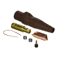
ITEMS AND TOOLS NEEDED FOR ASSEMBLY
• (1) Razor Cutting Blade • (1 or 2) Copper Shim(s)*† • (1) Flat Head Screw Driver • (1 or 2) Hex Head Socket Set Screw(s)*†
• (1) Allen Wrench • (1) Thermoplastic Captivating Screw* • (1) Pliers • (1) Strain Relief Wire*†
• (1) Can of Leviton Spray Lube • (1) Contact & Sleeve (Same Sex)* • (1) Wire Cutter • (1) Com-a-Long tool
* Provided
†Depending on model
INSTALLATION INSTRUCTIONS
WARNING: TO BE INSTALLED AND/OR USED IN ACCORDANCE WITH ELECTRICAL CODES AND REGULATIONS.
WARNING: IF YOU ARE NOT SURE ABOUT ANY PART OF THESE INSTRUCTIONS, CONSULT AN ELECTRICIAN.
WARNING: USE “CU” CABLE ONLY. DO NOT EXCEED RATED CABLE AMPACITY FOR CORRESPONDING CABLE SIZE. ACCEPTABLE CORD TYPES INCLUDE; SC, SCE, SCT, OR TYPE “W”.
CAUTION: FEMALE CONTACTS FOR TAPER NOSE AND BALL NOSE DEVICES ARE NOT INTERCHANGABLE. TAPER NOSE ASSEMBLIES WILL NOT MATE PROPERLY WITH BALL NOSE ASSEMBLIES.
NOTE: INSULATING JACKETS ON POWER CABLES ARE NOT OF UNIFORM THICKNESS. THE CABLE SIZE INDICATORS LISTED ON OUR SLEEVES ARE ONLY GUIDELINES FOR TRIMMING TO THE CORRECT CABLE DIAMETER.
DO NOT PRECUT SLEEVES BEFORE YOU ARE READY TO ASSEMBLE.
NOTE: USE AMPACITY CHART FOR CORRECT CABLE SIZE APPLICATION.
TO ASSEMBLE:
1. WARNING: TO AVOID FIRE, SHOCK OR DEATH, TURN OFF POWER AT CIRCUIT BREAKER OR FUSE AND TEST THAT THE POWER IS OFF BEFORE WIRING!
2. Hold the cable end of the sleeve to your power cable to establish an idea of how much of the sleeve to cut off taking into account the sleeve thickness. Be sure to cut conservatively.
Example: For a 2/0 cable, cut below the 1/0 line of the sleeve for your initial cut. If the hole is too small, take off a little more until you have a good, snug t over the cable.
3. Spray Leviton Silicone Spray Lube into the sleeve and onto the cable end (you can also use liquid soap or cable pulling compound). Slide the sleeve over the cable as shown in Figures 1A, 1B, 2A & 2B.
NOTE: DO NOT coat contact or inside diameter of sleeve where contact ts, as this may cause the contact to slip within sleeve.
4. Strip approx. 1-7/16” of the jacket off the cable end (refer to Figures 1A, 1B, 2A & 2B). Wrap 1 or 2 copper shims around the exposed wire depending on your cable size.
NOTE: Wrap the center of the strain relief wire around the cable jacket between 3/8” and 1/2” from the end of the jacket and tighten by twisting with pliers.
5. Bend the wire so that it rests at against the shim making sure to squeeze the twisted portion tightly against the cable jacket to ensure that it will clear the locking ring inside the insulator.
6. Cut the ends of the strain relief wire ush with the front end of the shim. Once secured, the strain relief wire will prevent the cable jacket from pulling away from the connector.
7A. For Set Screw devices: Insert the exposed cable all the way into the contact with the strain relief wire opposite the hex socket set screw holes. Using an Allen wrench, tighten the 1/2-20 set screws to 120 in.-lbs. of torque, ensuring that they
are rmly secure. Coat cable jacket and contact as in step 3 and slide the sleeve over the contact until the screw port in the sleeve is aligned with the threaded 3/8-16 captivating screw hole in the contact.
NOTES:
• It is easier to mate two contacts together to assist you in this procedure.
• The captivating screw hole in the contact is in line with the at part of the cam for the males and with the guide boss for the females.
• Use Com-a-Long tool to push contact into sleeve, if necessary.
7B. For Crimp devices: Insert the exposed cable and strain relief wire all the way into the contact. Crimp the copper tube using a Burndy Type 644 Dieless Crimp Tool for all wire sizes. Coat cable jacket and contact as in step 3 and slide the sleeve
over the contact until the screw port in the sleeve is aligned with the threaded 3/8-16 captivating screw hole in the contact.
NOTES:
• It is easier to mate two contacts together to assist you in this procedure.
• The captivating screw hole in the contact is in line with the at part of the cam for the males and with the guide boss for the females.
• Use Com-a-Long tool to push contact into sleeve, if necessary.
8. Once the holes in the contact and sleeve are aligned, insert the thermoplastic captivating screw and tighten down to 16 in.-lbs. of torque using a at head screwdriver.
9A. For Set Screw devices: To disassemble, reverse the process (refer to step 7A).
9B. For Crimp devices: To disassemble, reverse the process and remove contact by cutting off (refer to step 7B).
English
Screw Port
Orifice
Entrada para tornillo
Screw Port
Orifice
Entrada para tornillo
Cable
Câble
Cable
Câble
Cable
Câble
Cable
Câble
Contact
Contacteur
Contacto
Contact
Contacteur
Contacto
1/2"
1.3 cm
1/2"
1.3 cm
1-7/16"
1.0 cm
1-7/16"
1.0 cm
Male Com-a-Long
Com-a-Long mâle
Jalador Macho
Set Screws
Vis hexagonales
Tornillos
Screw Hole
Trou
Hueco para el tornillo
Screw Hole
Trou
Hueco para el tornillo
Set Screws
Vis hexagonales
Tornillos
Female Com-a-Long
Com-a-Long femelle
Jalador Hembra
Male Sleeve
Manchon mâle
Manga macho
Female Sleeve
Manchon femelle
Manga hembra
Crimp Tube
Tube à sertir
Tubo plegador
Crimp Tube
Tube à sertir
Tubo plegador
Screw Port
Orifice
Entrada para tornillo
Screw Port
Orifice
Entrada para tornillo
Cable
Câble
Cable
Câble
Cable
Câble
Cable
Câble
Contact
Contacteur
Contacto
Contact
Contacteur
Contacto
1/2"
1.3 cm
1/2"
1.3 cm
1-7/16"
1.0 cm
1-7/16"
1.0 cm
Screw Hole
Trou
Hueco para el tornillo
Screw Hole
Trou
Hueco para el tornillo
Female Com-a-Long
Com-a-Long femelle
Jalador Hembra
Male Sleeve
Manchon mâle
Manga macho
Female Sleeve
Manchon femelle
Manga hembra
Male Com-a-Long
Com-a-Long mâle
Jalador Macho
Figure 1 / Figura 1
16 Series Male and Female - Set Screw
Connecteurs mâles et femelles à visser (série 16)
Macho y Hembra Serie 16 - Tornillo
Screw Port
Orifice
Entrada para tornillo
Screw Port
Orifice
Entrada para tornillo
Cable
Câble
Cable
Câble
Cable
Câble
Cable
Câble
Contact
Contacteur
Contacto
Contact
Contacteur
Contacto
1/2"
1.3 cm
1/2"
1.3 cm
1-7/16"
1.0 cm
1-7/16"
1.0 cm
Screw Hole
Trou
Hueco para el tornillo
Screw Hole
Trou
Hueco para el tornillo
Female Com-a-Long
Com-a-Long femelle
Jalador Hembra
Male Sleeve
Manchon mâle
Manga macho
Set Screws
Vis hexagonales
Tornillos
Set Screws
Vis hexagonales
Tornillos
Male Com-a-Long
Com-a-Long mâle
Jalador Macho
Female Sleeve
Manchon femelle
Manga hembra
Screw Port
Orifice
Entrada para tornillo
Screw Port
Orifice
Entrada para tornillo
Cable
Câble
Cable
Câble
Cable
Câble
Cable
Câble
Contact
Contacteur
Contacto
Contact
Contacteur
Contacto
1/2"
1.3 cm
1/2"
1.3 cm
1-7/16"
1.0 cm
1-7/16"
1.0 cm
Screw Hole
Trou
Hueco para el tornillo
Screw Hole
Trou
Hueco para el tornillo
Female Com-a-Long
Com-a-Long femelle
Jalador Hembra
Male Sleeve
Manchon mâle
Manga macho
Crimp Tube
Tube à sertir
Tubo plegador
Crimp Tube
Tube à sertir
Tubo plegador
Male Com-a-Long
Com-a-Long mâle
Jalador Macho
Female Sleeve
Manchon femelle
Manga hembra
Figure 2 / Figura 2
18 Series Male and Female - Crimp
Connecteurs mâles et femelles à sertir (série 18)
Macho y Hembra Serie 18 - Plegable
NOTE: In open air, based on ambient temperature of 30° C. (86° F.)
REMARQUE : à l’air libre et à une température ambiante 30° C (86° F)
NOTA: Al aire libre, basado en temperatura de ambiente de 30° C (86° F)
Allowable Device Ampacity Chart
Tableau des courants admissibles
Cuadro de amperaje permitido para el producto
Cable Size AWG
Calibre de Câble (AWG)
Tamaño del Câble (AWG)
75° C. Cable
Isolant résistant à Cable 75° C.
Cable de 75° C.
90° C. Cable
Isolant résistant à Cable 90° C.
Cable de 90° C.
#2 170 190
#1 195 220
1/0 230 260
2/0 265 300
3/0 310 350
4/0 360 400
PK-92942-10-02-0C