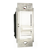
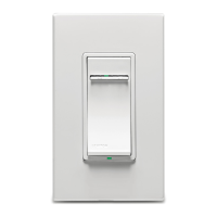
Connect wires per WIRING DIAGRAM as follows:
Screw wire nuts on clockwise making sure no bare
conductors show below the wire connectors. Secure each
connector with electrical tape.
WARNING: CONNECT AN ELECTRONIC LOW-VOLTAGE
DIMMER ONLY TO THE PRIMARY (HIGH-VOLTAGE) SIDE
OF A ELECTRONIC LOW-VOLTAGE TRANSFORMER.
NOTE: Dimmer can be installed on either the Load or Line side.
• Green dimmer Ground lead to Green or bare copper
wire in wall box.
• Black dimmer lead to tagged (common) wall box wire identied
when removing old switch.
• White dimmer lead to White Neutral wall box wire.
• Remove Red insulating label from Red lead.
• Any Red dimmer lead to any of the remaining wall box wires.
• Remaining Red dimmer lead to remaining wall box wire.
Testing your Dimmer prior to mounting in wall
box:
Dimmer Mounting:
TURN OFF POWER AT CIRCUIT BREAKER OR FUSE.
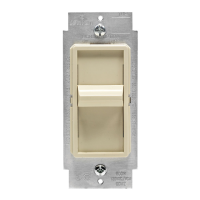
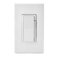
Single-Pole Wiring Application using 3-Way
Dimmer:
Connect wires per WIRING DIAGRAM as follows:
Screw wire nuts on clockwise making sure no bare conductors
show below the wire connectors. Secure each connector with
electrical tape.
WARNING: CONNECT AN ELECTRONIC LOW-VOLTAGE
DIMMER ONLY TO THE PRIMARY (HIGH-VOLTAGE) SIDE OF
A ELECTRONIC LOW-VOLTAGE TRANSFORMER.
• Green dimmer Ground lead to Green or bare copper wire in
wall box.
• Black dimmer lead to any wall box wire removed from old
switch.
• White dimmer lead to White Neutral wall box wire.
• Red dimmer lead without insulating label to remaining wall
box wire.
• Remaining Red dimmer lead should have Red insulation label
afxed. Proceed to Step 6.
NOTE: If insulating label is not afxed to Red lead, use a
small wire nut or electrical tape to cap off. Proceed to Step 6.
3-Way Wiring Application:
LIMITED 5 YEAR WARRANTY AND EXCLUSIONS
Leviton warrants to the original consumer purchaser and not for the benet of anyone else that this product at the time of its sale by Leviton is free of defects in materials and workmanship under normal and proper use for ve years from the purchase date. Levitonʼs only
obligation is to correct such defects by repair or replacement, at its option, if within such ve year period the product is returned prepaid, with proof of purchase date, and a description of the problem to Leviton Manufacturing Co., Inc., Att: Quality Assurance Department,
59-25 Little Neck Parkway, Little Neck, New York 11362-2591. This warranty excludes and there is disclaimed liability for labor for removal of this product or reinstallation. This warranty is void if this product is installed improperly or in an improper environment, overloaded,
misused, opened, abused, or altered in any manner, or is not used under normal operating conditions or not in accordance with any labels or instructions. There are no other or implied warranties of any kind, including merchantability and tness for a particular purpose, but
if any implied warranty is required by the applicable jurisdiction, the duration of any such implied warranty, including merchantability and tness for a particular purpose, is limited to ve years. Leviton is not liable for incidental, indirect, special, or consequential damages,
including without limitation, damage to, or loss of use of, any equipment, lost sales or prots or delay or failure to perform this warranty obligation. The remedies provided herein are the exclusive remedies under this warranty, whether based on contract, tort or otherwise.
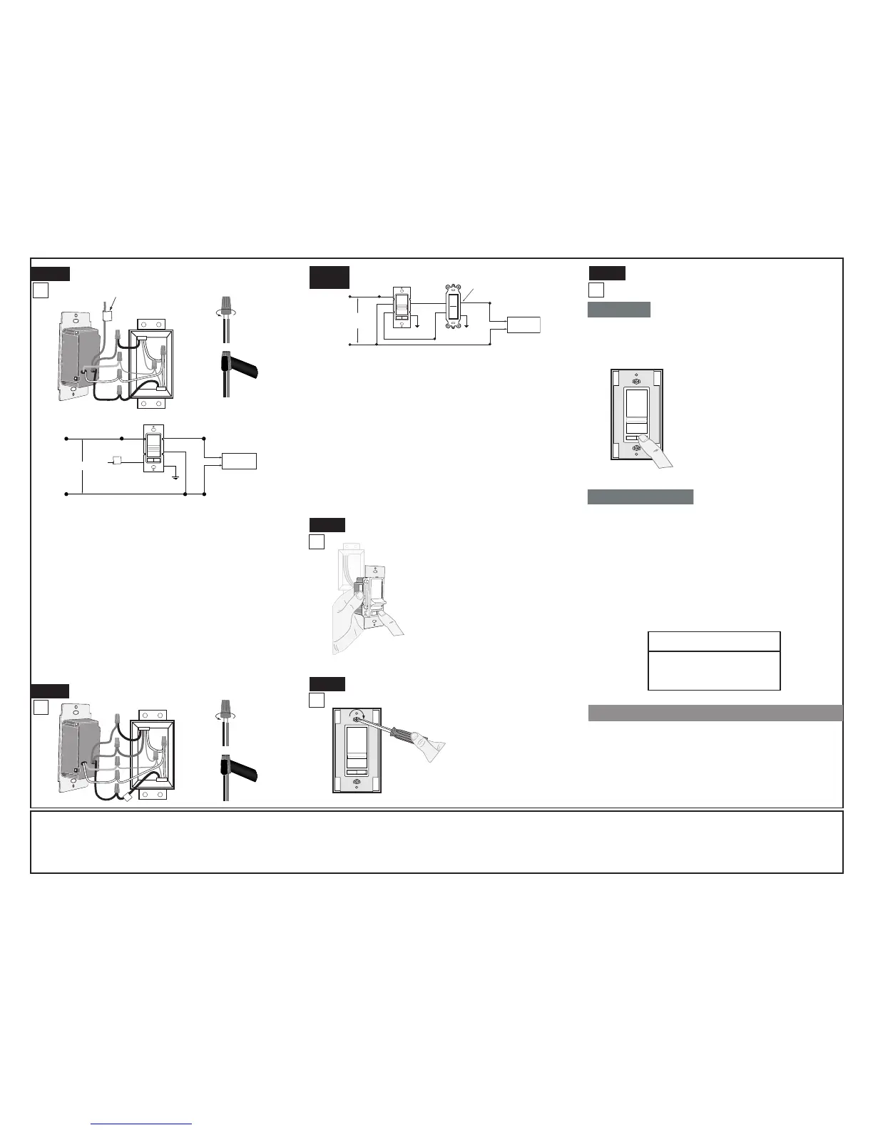
• Restore power at circuit
breaker or fuse.
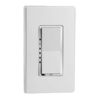
• Carefully holding Dimmer as
shown, slide control lever to
highest postion. If lights are not
ON, press rocker. Lights should
turn ON to brightest level.
If lights do not turn ON, refer
to the TROUBLESHOOTING
section.
Step 5b
Step 6
Step 7
Installation may now be
completed by carefully
positioning all wires to
provide room in wall box
for dimmer. Mount dimmer
into box with mounting
screws supplied. Attach
Decora
®
wallplate.
Restore Power: Restore power at circuit breaker or
fuse. Installation is complete.
OPERATION
NOTE: If using the dimmer in a 3-way application, the lights will
turn ON at the level the slider is set for both single pole and 3-way
applications. The lighting can be controlled from either the dimmer
or the switch location.
TROUBLESHOOTING
• Lights Flickering
- Lamp has a bad connection.
- Wires not secured rmly with wire connectors.
• Light does not turn ON
- Circuit breaker or fuse has tripped.
- Lamp is burned out.
- Lamp Neutral connection is not wired.
NOTE: If further information is needed in identifying the HOT wire
in a 3-Way application, go to Leviton's website at www.leviton.com.
 Loading...