EasyManua.ls Logo

Leviton a-2000 User Manual

Leviton a-2000
85 pages
To Next Page IconTo Next Page
Page #1 background imageLoading...
Page #1 background image
User Guide
a-2000
TM
DIMMER CABINET WITH
DIGITAL CONTROLS
12 & 24 CIRCUIT VERSIONS
Software revision 2.40 and above
COMMUNICATION PORTS
FULL BRIGHT
AUXILIARY
LUMANET
PHASE LOSS
DMX
FAN
R
BRIGHT
SELECT
CANCEL
FULL
SAVE
CLEAR
INDUSTRIAL CONTROL EQUIPMENT
TUALATIN, OR
32300A
R
MADE IN U.S.A.
a-2000
R
TM
LISTED
88H9
C
R
20
20
20
MODULE
MODULE
9
8
20
20
20
20
20
20
20
20
20
20
20
MODULE
MODULE
BYPASSNORMAL
7
6
MODULE
MODULE
MODULE
BYPASSNORMAL
5
4
3
20
20
20
20
20
20
20
B
MODULE
MODULE
BYPASSNORMAL
C
PHASE
2
1
CONTROL
PHASE
A
PHASE
10
MODULE
11
12
MODULE
MODULE
NORMAL BYPASS
20
20
20
20
20
20

Table of Contents

Question and Answer IconNeed help?

Do you have a question about the Leviton a-2000 and is the answer not in the manual?

Leviton a-2000 Specifications

General IconGeneral
ModelA-2000
Control TypeRotary
Mounting TypeWall Mount
ColorWhite
Voltage120 VAC
CompatibilityIncandescent

Summary

Overview

Feed and Load Wiring

Warnings

General Safety Precautions

Lists essential safety precautions for installation and operation, including professional installation and electrical codes.

Installation

Step 1: Mounting

Main Feed and Load Wiring

Step 3: Load Circuit Wiring - 120 Volt Units

Step 4 - Relay Cabinet (OPTIONAL)

Step 5: Control Input Wiring

Luma-Net® III Control System

Power Considerations and Run Lengths

Discusses control system planning, power supply, run lengths, and load rating verification.

Testing the Wiring

Wiring Test Procedure

Provides a recommended procedure for testing system wiring for shorts and opens.

DMX-512 Control System

DMX Wiring and Recommendations

Shows DMX wiring schematics and recommends specific wire types and grounding.

Analog Input, 0-10 VDC (Optional)

External Full On/Emergency (Full Bright)

External Full Bright Trigger Operation

Explains the external trigger for forcing selected dimmers to full bright via a contact closure.

Step 6: Fluorescent Dimming and Control Output Wiring

Dimmer Module Installation

Module Installation and Replacement Procedures

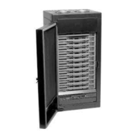
Details the process of installing or replacing dimmer modules, including blanking plates.

Step 8: Bypass Mode

Bypass Switch Operation and Considerations

Explains bypass switch modes for 120V units and special considerations for 0-10 VDC ballasts.

Installation Steps 9-12

Final Installation Checks and Power-Up

Covers double-checking wiring, powering on, clearing faults, and setting bypass switches to normal.

Digital Control Panel

Step 13: Configuration and Programming

LCD Display Menu Structures Overview

Refers to figures showing menu structures for programming the a-2000 cabinet.

Main Menu Screens Overview

Displays the main menu screens and their navigation flow.

Module Set Up Screen Hierarchy

Shows the various module setup screens and their hierarchical structure.

Step 13A: Display at Startup

Step 13D: Modify the Dimmer Type Features

Assign the Module/Load Type

Module/Load Type Assignment Procedure

Guides users through assigning module and load types via the setup code and menu.

Step 13E: Verifying Module Programming

Module Programming Verification

Explains how to check programmed settings for dimmer modules using the LCD display.

Step 13F: Assigning Luma-Net and/or DMX512 Channels

Step 13G: Daylight Harvesting/Photocells

Step 13H: Modifying Factory Defaults

Specifications

Types of Dimmer Modules

Power Considerations for Control Systems

Related product manuals