EasyManua.ls Logo

Leviton RENOIR II AWRMG-I Series User Manual

Leviton RENOIR II AWRMG-I Series
2 pages
To Next Page IconTo Next Page
Page #1 background imageLoading...
Page #1 background image
RENOIR II
INCANDESCENT/MAGNETIC LOW VOLTAGE NO NEUTRAL DIMMING CONTROL
Cat. Nos. AWRMG-IXX, AWSMG-IXX & AWSMT-IXX
INSTALLATION
WARNINGS AND CAUTIONS:
฀TO AVOID FIRE, SHOCK OR DEATH; TURN OFF POWER AT CIRCUIT BREAKER OR FUSE AND TEST THAT POWER IS OFF BEFORE WIRING!
฀TO BE INSTALLED AND/OR USED IN ACCORDANCE WITH ELECTRICAL CODES AND REGULATIONS.
฀IF YOU ARE NOT SURE ABOUT ANY PART OF THESE INSTRUCTIONS, CONSULT AN ELECTRICIAN.
฀DO NOT GANG VERTICALLY.
฀ONLY INSTALL FOR THE ALLOWED LOAD TYPES. INSTALLATION FOR ANY OTHER LOAD TYPE WILL VOID WARRANTY AND POSSIBLY CAUSE DAMAGE TO
THIS DEVICE AND/OR CONNECTED EQUIPMENT.
฀USE THIS DEVICE WITH COPPER OR COPPER CLAD WIRE ONLY.
Installation Requirements:
฀฀฀฀฀฀฀฀฀฀฀฀฀฀฀฀฀
฀฀฀฀฀฀฀฀฀฀฀฀฀
฀฀฀฀฀฀not฀฀฀฀฀฀
฀฀฀฀฀฀฀฀฀฀฀฀฀฀
฀฀฀฀฀฀฀฀฀฀
฀฀฀฀฀฀฀฀฀฀
฀฀฀฀฀฀฀฀฀฀฀฀฀
฀฀฀฀฀Multi-Gang Installations฀฀
฀
฀
฀฀฀฀฀฀฀฀฀฀
฀฀฀
฀฀฀฀฀฀฀฀฀฀฀฀฀
฀฀฀฀฀฀฀฀฀฀฀฀฀
฀฀฀฀฀(See Figure 2).
Installation Instructions:
1. WARNING: TO AVOID FIRE, SHOCK OR DEATH; TURN OFF POWER AT
CIRCUIT BREAKER OR FUSE AND TEST THAT POWER IS OFF BEFORE
WIRING!
2.฀฀฀฀฀฀฀
3.฀฀฀฀฀฀฀฀฀฀฀฀฀฀
฀฀฀฀฀
4.฀฀฀฀฀฀฀฀฀฀฀฀
฀฀฀฀฀฀฀฀฀฀฀฀฀

5.฀฀฀฀฀฀฀฀(see Figure 3).
฀฀฀
6.฀฀฀฀฀฀Installation is complete.
7.฀฀
INPUT - 120 VAC 60 HZ
฀฀฀
฀฀฀
฀฀฀
฀฀฀
Features and Operation:
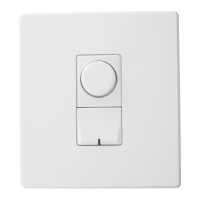
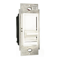
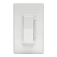
฀฀฀฀฀฀฀฀฀฀฀฀฀฀฀฀฀
฀฀฀฀฀฀฀฀฀฀฀฀฀฀฀
฀฀฀฀฀฀฀฀฀฀฀฀฀฀฀
฀฀฀฀฀฀฀฀฀฀฀฀฀฀฀฀฀

฀฀฀฀฀฀฀฀฀฀฀฀฀฀฀
฀฀฀฀฀฀฀฀฀฀฀฀฀฀
฀฀฀฀฀฀฀฀฀฀฀฀฀
฀฀฀฀฀฀฀฀฀฀฀฀฀฀
฀฀฀฀฀฀฀฀฀฀฀฀฀฀฀฀
฀฀฀฀฀฀฀฀฀฀฀฀฀฀฀฀
฀฀฀฀฀฀฀฀฀฀฀฀฀
฀฀฀฀฀฀฀฀฀฀฀฀฀฀฀
฀฀฀฀฀฀฀฀฀฀
฀฀฀฀฀฀฀฀฀฀฀฀฀
฀฀฀฀฀฀฀
฀฀฀฀฀฀฀฀฀฀฀฀฀฀฀฀
฀฀฀฀฀฀฀
฀฀฀฀฀฀฀฀฀฀฀฀฀฀
฀฀฀฀฀฀฀฀฀฀฀฀฀
฀฀฀฀
฀฀฀฀฀฀฀฀฀฀฀฀฀฀฀
฀฀฀฀฀฀฀฀฀฀฀฀฀฀
฀฀฀฀฀฀฀฀฀฀฀฀฀฀฀฀
฀฀฀฀฀฀฀฀฀฀฀฀฀฀฀
฀฀฀฀
฀฀฀฀฀฀฀฀฀฀฀฀฀฀฀
฀฀฀฀฀฀฀฀฀฀
฀฀฀฀฀฀฀฀฀ Figure 1.
฀฀฀฀฀฀฀
LIMITED 5 YEAR WARRANTY AND EXCLUSIONS
฀฀฀฀฀฀฀฀฀฀฀฀฀฀฀฀฀฀฀฀฀฀฀฀฀฀฀฀฀฀฀฀฀฀฀฀฀฀฀฀฀฀฀฀฀฀฀฀
฀฀฀฀฀฀฀฀฀฀฀฀฀฀฀฀฀฀฀฀฀฀฀฀฀฀฀฀฀฀฀฀฀฀฀฀฀฀฀฀฀฀฀฀฀
฀฀฀฀฀฀฀฀฀฀฀฀฀฀฀฀฀฀฀฀฀฀฀฀฀฀฀฀฀฀฀฀฀฀฀฀฀฀฀฀
฀฀฀฀฀฀฀฀฀฀฀฀฀฀฀฀฀฀฀฀฀฀฀฀฀฀฀฀฀฀฀฀฀฀฀฀฀฀฀฀฀฀฀
฀฀฀฀฀฀฀฀฀฀฀฀฀฀฀฀฀฀฀฀฀฀฀฀฀฀฀฀฀฀฀฀฀฀฀฀฀฀
฀฀฀฀฀฀฀฀฀฀฀฀฀฀฀฀฀฀฀฀฀฀฀฀฀฀฀฀฀฀฀฀฀฀฀฀฀฀฀฀

Align flats when
installing knob
Center tab in opening
฀฀฀฀฀
฀฀
Wiring Diagram
Dimming Control
LOAD
Black
Blue
Neutral (White)
Hot (Black)
White
Yellow
For use in multi-way
control (remote)
applications.
Cap wire if not used.
Ground (Green)
Line
120VAC
60 Hz
฀฀฀฀฀฀฀
Blue
Hot (Black)
Neutral (White)
White
White
Load
Blue
Black
Black
Yellow
Yellow
Green
Ground
Hot (Black)
Neutral (White)
Load
Run a separate neutral wire
for each load circuit
Run a separate neutral wire
for each load circuit
Green
Ground
Service Switch
Load
Connected
Load
Disconnected
Service Switch
Load
Connected
Load
Disconnected
฀฀฀฀฀
฀฀
WEB VERSION
Question and Answer IconNeed help?

Do you have a question about the Leviton RENOIR II AWRMG-I Series and is the answer not in the manual?

Leviton RENOIR II AWRMG-I Series Specifications

General IconGeneral
BrandLeviton
ModelRENOIR II AWRMG-I Series
CategoryDimmer
LanguageEnglish

Summary

INSTALLATION

WARNINGS AND CAUTIONS

Crucial safety warnings to prevent fire, shock, or death before installation and wiring begins.

Features and Operation

Details how to turn the device on/off, set levels, and use special features like preset and power restore.

Installation Requirements

Specifies required back box sizes, multi-gang considerations, and rules against vertical installation.

Installation Instructions

Provides a step-by-step guide for wiring, mounting, and completing the device installation process.

Wiring Diagram

Illustrates the electrical connections for the dimming control and multi-way setups using diagrams.

MULTI-GANG INSTALLATIONS

De-ratings

Explains how removing fins in multi-gang installations affects device performance and requires de-rating.

Fin Removal

Details the process of breaking off internal fins to fit multiple devices into compact wallboxes.

Multi-Way Control

Covers support for 5-way control using combinations of dimmers, switches, and remotes.

Related product manuals