Page 38
Step 6: Fluorescent Dimming and Control Output
Wiring
Many installations incorporate fluorescent dimming ballasts into some or all of the
fluorescent fixtures. Refer to the Appendix section for general information about
dimming ballasts, their use and their control methods.
For best lamp life, lamp manufacturers recommend their fluorescent
lamps should be operated at full brightness for a minimum or 100 hours
before dimming is permitted. For best results, lamp brands and types
should not be intermixed on a circuit.
Types of Dimming Ballasts
• 0-10 volt DC control
• Two Wire Ballasts
• Three Wire ballasts
0-10 volt DC control:
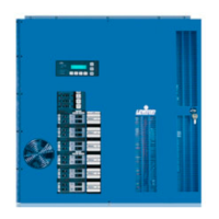
These ballasts require that the low voltage wires (typically Violet and Grey) are
landed on the Dimming Ballast Output terminals located on the Control Modules
main circuit board.
The control output channels are auto assigned. The control wire
for the first M7 dimmer will be the first control terminal, and the
second M7 dimmer will be the second terminal, even though
there are other dimmers of different types in between.
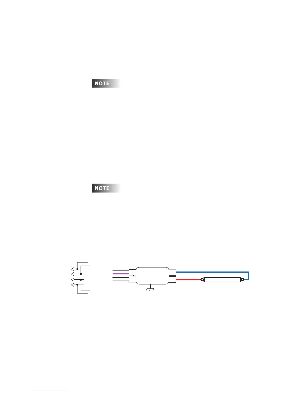
Figure 26 - 0-10 VDC Ballast Control Wiring
Ballast
L a m p
Switched Hot-
Neutral-
0-10V DC
Control
To
Dimmer
Cabinet
To Next
Ballast
Gray
Violet
Black
White
Mount to
Grounded
Fixture
}
0-10 Volt DC Wire Schematic
Note: drawing shows one lamp, but can be
applied to 2,3, and 4 lamp ballast versions.