a-2000 User Guide
a-2000 Page 23
Dimmer Cabinets with Digital Controls
Revision G November 2006
Low Voltage Control Wiring
Step 5: Control Input Wiring
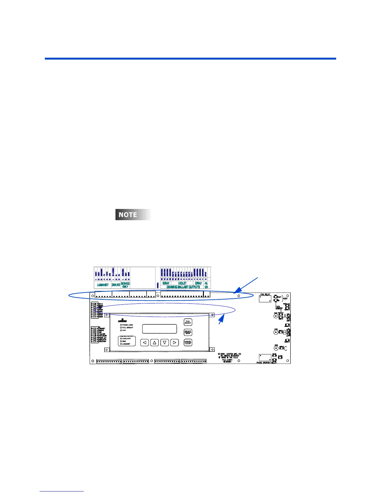
Once the power wiring has been completed, control wiring can be addressed. The
upper left side of the dimmer cabinet is reserved for control wiring. Refer to
Figure 4 and 28 for the location of the control module and the low voltage wire
way. Terminate all control wiring directly to the terminal blocks on the printed
circuit card found in the upper left location. Use a small 1/8-in. flat screwdriver on
these terminals.
Wire Range:
•24-12 AWG, Stranded, Torque to 9 in-lbs.
•16-8 AWG, Stranded, Torque to 18-20 in-lbs. for 24 Channel power supply
terminals
The digital control panel can accept the following control signals:
• Luma-Net® III
• DMX512
• Analog 0-10VDC Inputs - Available as an Option
See the Appendix for a full description of the various control inputs
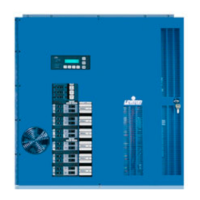
Figure 13 - Digital Control Module
Control Wiring
Terminal Blocks
0-10 VDC Ballast Outputs
Optional! Analog
Connectors