a-2000 User Guide
a-2000 Page 29
Dimmer Cabinets with Digital Controls
Revision G November 2006
If a remote DC power supply is used and you have multiple Luma-Net
runs, all DC common wires must be joined at the power supply.
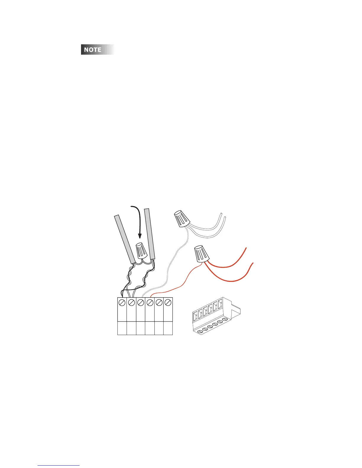
Wiring the Phoenix Connector
Step 1: Connect leads per wiring diagram as illustrated in Figure 18.
Step 2: Twist strands of each lead tightly (making sure that there are no
stray strands) and push firmly into appropriate plug connector
location.
Step 3: Tighten the screws on the plug connector—making sure that no bare
conductor is showing.
Step 4: Tie the Drain/Shield wires together and insulate using a small piece
of heat shrink tubing.
Step 5: Install termination jumpers as required. Termination jumpers are
required at the two ends of the Luma-Net run.
Figure 17 - Luma-Net Wiring Connections
REM+
REM -
COM
TERM
N/C
+V
1
2
3
4
5
6
Upto1#12AWG
2#14AWG min.
2#14AWG min.
Up to 1 #12AWG
Drain/Shield - Insulated and tied together
(Ground at one point only-
probably an end)
Red
(+V )
Black (Common)
5
6
1
2
3
4
Phoenix Connector