a-2000 User Guide
a-2000 Page 69
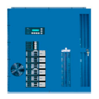
Dimmer Cabinets with Digital Controls
Revision G November 2006
Appendix A
Control Inputs
Luma-Net® III
The most common input is Luma-Net III, a Leviton protocol, that sends serial
digital data over a twisted pair of communication (data) wires. With this system,
controls can be located up to 2000 ft. from the dimming cabinet. The two data
wires terminate on REM+ and REM- of the Luma-Net Terminal Block. Any shield if
present is not connected.
Along with this pair of communications (data) wires are a second pair of wires for
providing current limited 24 VDC power to operate displays and electronics in the
remote control stations. These wires terminate on COM and +V. The
communications signals require very little power, and number 24 AWG wire is
adequate for the twisted pair. Belden number 9729 or equivalent is
recommended. However the 24 VDC power wires handle more current and should
be a #14 AWG minimum wire to insure that only a very small amount of voltage
drop takes place over long distances. If a remote DC power supply is used, all DC
common wires must be joined.
Where more than one remote control panel or dimmer cabinet using Luma-Net III
communications is used in a system, the data wires and the DC power wires are
run together from the dimmer cabinet to the nearest control station, then on to
the next station, and the next, and so on. At the last control station or dimmer
cabinet on both ends of the run, a small jumper wire must be run from the
terminal labeled “Rem-” to the terminal marked “Term” on that last station. This
jumper wire properly terminates the digital communications lines at the end of
the line. Shield to ground at one point only.
DMX512
The digital control panel accepts DMX-512 signals, an industry standard signal
widely used in the theater industry. This offers the opportunity to use theatrical
consoles to control some or all of the dimmers in the a-2000D Dimmer Cabinet.
Analog
The digital control panel accepts a third type of control signal often used with
analog control systems, if equipped with the optional analog control card. This
signal varies between 0 VDC and +10 VDC to control the dimmer outputs. An
input of 0 V results in no output power from the dimmer; an input of +10 VDC
gives full voltage output from the dimmer. Varying this signal from 0 VDC to
+10 VDC varies the AC output voltage from zero to virtually full line voltage. If
this system uses analog inputs, an optional analog control card will have been
added during fabrication.
Multiple Signal Types
Under certain circumstances the digital control panel can receive two or more
types of input signals.
See page 34.