WARNINGS AND CAUTIONS:
• TO BE INSTALLED AND/OR USED IN ACCORDANCE WITH APPROPRIATE ELECTRICAL CODES AND REGULATIONS.
• IF YOU ARE NOT SURE ABOUT ANY PART OF THESE INSTRUCTIONS, CONSULT AN ELECTRICIAN.
• DO NOT CONNECT LINE VOLTAGE WIRES TO LOW VOLTAGE TERMINALS.
• FOR THE BEST LAMP LIFE, LAMP MANUFACTURERS RECOMMEND THEIR FLUORESCENT LAMPS SHOULD BE OPERATED AT FULL BRIGHTNESS FOR A MINIMUM
OF 100 HOURS BEFORE DIMMING IS PERMITTED. FOR BEST RESULTS, LAMP BRANDS AND TYPES SHOULD NOT BE INTERMIXED ON A CIRCUIT.
• DISCONNECT POWER WHEN SERVICING THE DIMMER, FIXTURE OR WHEN CHANGING LAMPS.
• FOR INDOOR USE ONLY.
• TO AVOID FIRE, SHOCK OR DEATH: TURN OFF POWER AT MAIN CIRCUIT BREAKER OR FUSE AND TEST THAT THE POWER IS OFF BEFORE WIRING!
INTRODUCTION:
For best results using the Dimensions 4200 Architectural Lighting Controller, Follow these recommendations:
1. Plan the system before beginning the installation 6. Program each Station
2. Terminate the wiring Assign unique network ID numbers to stations.
3. Test the wiring Connect one master station, and then one remote control station at a time.
4. Connect dimmer cabinets Verify that the first D4200 can properly control the dimmers assigned to it.
5. Power up the Stations Check the proper operation of each station as it is installed when multiple stations are involved.
7. Install all Stations
NOTE: If the lighting control fails or becomes sporadic, first check the wiring or network ID.
MINIMUM BACK BOX DIMENSIONS:
• NEMA (US) markets: 1 gang device back box, 1-1/2" deep.
• For IEC (3x3) markets: 1 gang device back box, min 35mm deep, 47mm preferred.
Minimum vertical clearance 69mm, minimum horizontal clearance 45mm.
Designed for horizontal screw mounting.
TERMINATING THE WIRING:
Luma-Net
®
III
Control Stations can be located up to 2000 ft. from the dimming cabinet. Luma-Net
®
is wired Daisy Chained, station to station. For applications where runs become too long a Hub
can be used. The cable should not pass near any source of electrical noise such as fluorescent circuits or motor wiring. Avoid close proximity to any AC wiring. All control/power
wiring must be in conduit.
Luma-Net
®
Wire Recommendations
Leviton strongly recommends the use of Belden 1502R or 1502P for Luma-Net
®
wire runs. Other Belden cables, ex: #9829 & 9729, or RS-485 cable compliant with the
specifications above, may also be used. Standard voltage drop for DC power systems can be used. Stations require a minimum of +10VDC in order to be effective.
1.
Use RS485 compatible cable for communications. It is recommended that a cable with 2 Twisted Pair, 24 AWG (min.), stranded conductors be used. The spare pair is for future uses.
2. Capacitance of wire shall be 15pF/ft. or less.
3. Normal Impedance of wire shall be between 100-120 ohms.
4. A second pair of stranded wire is required for the power.
5. Drain/Shields to be tied together, insulated and grounded at one point only.
If a remote DC power supply is used and you have multiple Luma-Net
®
runs, all DC common wires must be joined at the power supply.
At the last control station or dimmer cabinet on both ends of run, a small jumper wire must be run from the terminal labeled "Rem-" to the terminal marked "Term" on that last station.
This jumper wire properly terminates the digital communications lines at both ends of the line.
Wire the Phoenix Connector
1. Connect leads per wiring diagram (see Luma-Net
®
Wire Connections).
2. Twist strands of each lead tightly (making sure that there are no stray strands) and push firmly into appropriate plug connector location.
3. Tighten the screws on the plug connector-making sure that no bare conductor is showing.
4. Tie the Drain/Shield wires together and insulate using a small piece of heat shrink tubing.
5. Install termination jumpers as required. Remember a termination jumper is required at the two ends of the Luma-Net
®
run.
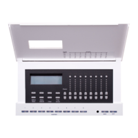
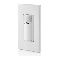
D4200 Remote Entry Stations
DI-000-D42XX-00B
D4200
CONTROL
STATION
PRESET
SELECT
STATION
C
12
18
15
16
17
13
14
6
9
10
11
7
8
3
4
5
1
2
A
B
DMX
CANCEL
LUMANET
CLEAR
PHASE LOSS
AUXILIARY
FULL BRIGHT
COMMUNICATION PORTS
FAN
SAVE
FULL
SELECT
BRIGHT
A-2000D
NOTE: A-2000D Cabinet can be in the middle of a daisy chain
D4200
CONTROL
STATION
PRESET
SELECT
STATION
A-2000D
17
16
18
10
11
14
13
15
12
5
8
7
9
6
B
2
4
3
C
1
A
LUMANET
DMX
CLEAR
CANCEL
FAN
COMMUNICATION PORTS
FULL BRIGHT
AUXILIARY
PHASE LOSS
BRIGHT
SELECT
FULL
SAVE
LUMA-NET
®
III HUB
D4200
CONTROL
STATION
PRESET
SELECT
STATION
A-2000D
17
16
18
10
11
14
13
15
12
5
8
7
9
6
B
A
LUMANET
DMX
CLEAR
CANCEL
FAN
COMMUNICATION PORTS
FULL BRIGHT
AUXILIARY
PHASE LOSS
BRIGHT
SELECT
FULL
SAVE
Drain/Shield - Insulated & tied together
(Ground at one point only - probably an end)
Termination
Jumper
2 #12AWG
2 #12AWG
Phoenix Connector Phoenix Connector
Black (Common)
Red (+V)
Up to 1 #12AWG
D4200
CONTROL
STATION
Terminate LumaNet in
these locations
Luma-Net
®
Wire Connections Luma-Net
®
Termination Jumper Locations
Ground Shield
(at one point only!)
PRESET
SELECT
STATION
A-2000D
REM+
REM -
COM
TERM
N/C
+V
1
2
3
4
5
6
5
6
1
2
3
4
C
12
18
15
16
17
13
14
6
9
10
11
7
8
3
4
5
1
2
A
B
DMX
CANCEL
LUMANET
CLEAR
PHASE LOSS
AUXILIARY
FULL BRIGHT
COMMUNICATION PORTS
FAN
SAVE
FULL
SELECT
BRIGHT
REM+
REM -
COM
TERM
N/C
+V
1
2
3
4
5
6
5
6
1
2
3
4