WARNINGS AND CAUTIONS:
• TOAVOIDFIRE,SHOCKORDEATH:TURNOFFPOWERATMAINCIRCUITBREAKERORFUSEANDTESTTHATTHEPOWERISOFFBEFOREWIRING,
SERVICINGTHEDIMMERORCHANGINGBULBS!
• DONOTCONNECTLINEVOLTAGEWIRESTOLOWVOLTAGETERMINALS.
• TOBEINSTALLEDAND/ORUSEDINACCORDANCEWITHELECTRICALCODESANDREGULATIONS.
• IFYOUARENOTSUREABOUTANYPARTOFTHESEINSTRUCTIONS,CONSULTANELECTRICIAN.
• FORINDOORUSEONLY.
• FORTHEBESTLAMPLIFE,LAMPMANUFACTURERSRECOMMENDTHEIRFLUORESCENTLAMPSSHOULDBEOPERATEDATFULLBRIGHTNESSFORAMINIMUMOF100HOURS
BEFOREDIMMINGISPERMITTED.FORBESTRESULTS,LAMPBRANDSANDTYPESSHOULDNOTBEINTERMIXEDONACIRCUIT.
INTRODUCTION:
ForbestresultsusingtheDimensions4200ArchitecturalLightingController,Followtheserecommendations:
1. Planthesystembeforebeginningtheinstallation
2. Terminatethewiring
3. Testthewiring
4. Connectdimmercabinets
5. PoweruptheStations
6. ProgrameachStation
AssignuniquenetworkIDnumberstostations.
Connectonemasterstation,andthenoneremotecontrolstationatatime.
VerifythattherstD4200canproperlycontrolthedimmersassignedtoit.
Checktheproperoperationofeachstationasitisinstalledwhenmultiplestationsareinvolved.
7. InstallallStations
NOTE:Ifthelightingcontrolfailsorbecomessporadic,rstcheckthewiringornetworkID.
TERMINATINGTHEWIRING:
Luma-Net
®
III
ControlStationscanbelocatedupto2000ft.fromthedimmingcabinet.Luma-Net
®
iswiredDaisyChained,stationtostation.Forapplicationswhererunsbecometoolongcontact
TechnicalSupportat1-800-959-6004.Thecableshouldnotpassnearanysourceofelectricalnoisesuchasuorescentcircuitsormotorwiring.AvoidcloseproximitytoanyACwiring.All
control/powerwiringmustbeinconduit.
Luma-Net
®
WireRecommendations
1.
UseRS485compatiblecableforcommunications.Itisrecommendedthatacablewith2TwistedPair,24AWG(min.),strandedconductorsbeused.Thesparepairisforfutureuses.
2. Capacitanceofwireshallbe15pF/ft.orless.
3. NormalImpedanceofwireshallbebetween100-120ohms.
4. Asecondpairofstrandedwireisrequiredforthepower.
5. Drain/Shieldstobetiedtogether,insulatedandgroundedatonepointonly.
WestronglyrecommendtheuseofeitherBelden9829,Belden9729orBelden1502R/1502PfortheLuma-Net
®
wireruns.
IfaremoteDCpowersupplyisusedandyouhavemultipleLuma-Net
®
runs,allDCcommonwiresmustbejoinedatthepowersupply.
Atthelastcontrolstationordimmercabinetonbothendsofrun,asmalljumperwiremustberunfromtheterminallabeled"Rem-"totheterminalmarked"Term"onthatlaststation.
Thisjumperwireproperlyterminatesthedigitalcommunicationslinesatbothendsoftheline.
WirethePhoenixConnector
1. Connectleadsperwiringdiagram(seeLuma-Net
®
WireConnections).
2. Twiststrandsofeachleadtightly(makingsurethattherearenostraystrands)andpushrmlyintoappropriateplugconnectorlocation.
3. Tightenthescrewsontheplugconnector-makingsurethatnobareconductorisshowing.
4. TietheDrain/Shieldwirestogetherandinsulateusingasmallpieceofheatshrinktubing.
5. Installterminationjumpersasrequired.RememberaterminationjumperisrequiredatthetwoendsoftheLuma-Net
®
run.
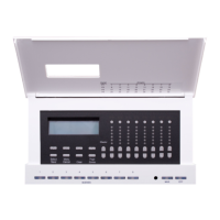
D4200A/VInterface
+9-24Vdc,50mA@12V,25mA@24V
DI-000-D42AV-00BAR2691
Drain/Shield - Insulated & tied together
(Ground at one point only - probably an end)
2 #12AWG
2 #12AWG
Phoenix Connector
Black (Common)
Red (+V)
Up to 1 #12AWG
®
REM+
REM -
COM
TERM
N/C
+V
1
2
3
4
5
6
5
6
1
2
3
4
Termination
Jumper
Phoenix Connector
®
Termination Jumper Locations
REM+
REM -
COM
TERM
N/C
+V
1
2
3
4
5
6
5
6
1
2
3
4
A-2000
DIMMER RACK
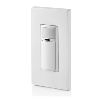
MASTER CONTROL STATION
MASTER CONTROL STATION
LUMA-NET HUB
BUTTON STATION
BUTTON
STATION
Figure 3 - Allowed star topology (with Luma-Net Hub only)
A-2000
DIMMER RACK
MASTER CONTROL STATION
MASTER CONTROL STATION
BUTTON
STATION
BUTTON STATION
Figure 2 - Dis-allowed star topology (DO NOT USE)
A-2000
DIMMER RACK
MASTER CONTROL STATION
MASTER CONTROL STATION
BUTTON
STATION
BUTTON
STATION
Figure 1 - Typical Daisy Chain wiring scenario