MINIMUM BRIGHTNESS ADJUSTMENT
1. Remove wallplate, if applicable.
2. If control is OFF when power is restored, turn control ON by tapping the upper-half of the rocker.
3. Using a small pointed object (i.e., small screwdriver), depress switch on side of dimmer (refer to Figure 2). Using the rocker,
adjust the brightness until light reaches lowest desired level (must be less than 1/3 full range). Release rocker. Release adjustment
lever and minimum brightness is set.
NOTE: You cannot turn OFF power to the light completely with the adjustment lever.
Once the minimum brightness level has been set, the unit automatically sets the display to indicate relative brightness as equally
distributed levels, to the maximum level of full brightness, which will vary according to bulb type and manufacturer.
4. When satisfied with the brightness level that you have selected, attach wallplate. Adjustment is complete.
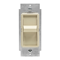
COLOR CONVERSION PROCEDURE
The color of Cat. Nos. HCM
Ø
6 and HCM1
Ø
can be changed to suit your interior design requirements. Simply obtain a color conversion
kit of the appropriate color from your Leviton distributor or use the one provided, and proceed as follows:
1. The switch plate has snaps on its sides. Place the tip of a small-bladed screwdriver under a snap and gently pry off the switch plate
(refer to Figure 1).
2. Take the new switch plate and position it properly to the strap. Notice that the switch plate has a cut-out for the air-gap switch lever.
With the switch plate properly positioned, gently press it into place until it seats properly with a click. The color conversion is
complete.
TO OPERATE
ON: Tap the upper half of the rocker. The lights will brighten to the last set light level.
OFF: Tap the lower half of the rocker. The lights will dim to OFF.
BRIGHTEN: Press and hold the upper half of the rocker to the desired light level.
FULL BRIGHT: Tap the upper half of the rocker twice quickly. The lights will turn ON FULL BRIGHT. The previous light level will remain
in memory upon next ON operation (see above).
DIM: Press and hold the lower half of the rocker to the desired level.
BRIGHTNESS LEVEL DISPLAY (HCM
Ø
6 AND HCM1
Ø
ONLY):
Indicates the level of brightness when the lights are ON. Indicates the previous level of brightness when the lights are OFF (refer to Figure 1).
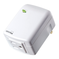
NOTE: To alert you that there is power to the dimmer when the load is OFF, the AC Indicator Light remains ON. To alert you that the
load is ON, the AC Indicator Light remains OFF.
NOTE: If lights are OFF, regardless if you tap or press and hold the upper half of the rocker, the lights will go to last set light level.
NOTE: If a power interruption should occur while the device is ON, the light load will return to its previous light level when power is restored.
TESTING PROCEDURE
With Cat. Nos. HCM
Ø
6 and HCM1
Ø
properly wired and powered-up, tap the switch plate several times to ensure that the module is
turning its load ON and OFF in response to manual control. To check for proper local dimming, keep switch plate pressed down to
confirm that load is dimming. Leave the switch in the ON position. Next, use a Cat. No. 6320, Leviton Table Top Controller, or any
other controller, to check for proper module operation as follows:
NOTE: If a power interruption should occur while the device is on, the light load will return to it’s previous state when power is restored.
1. Transmit an OFF command to the module. It should respond by turning its assigned Load OFF.
2. Transmit an ALL LIGHTS ON command to this module from an appropriately coded controller. It should respond by turning its
assigned Load ON.
3. Transmit DIM and BRIGHTEN commands. Lighting controlled should respond accordingly.
4. Transmit an ALL OFF command from an appropriately coded controller. It should respond by turning its assigned Load OFF.
PERFECT PERFORMANCE CHECKLIST
If Cat. Nos. HCM
Ø
6 and HCM1
Ø
appear to be functioning improperly, proceed with the following steps:
1. Confirm that the device is wired exactly as shown in the WIRING DIAGRAM.
2. Confirm that the module is being supplied from a 120V, 60Hz AC source ONLY.
3. Confirm that the load being controlled is in proper working order. Local switch, ON (check for burned-out bulbs).
4. Confirm that the Air Gap Switch Lever is pushed all the way in.
5. Confirm that the load being controlled does not exceed the 600W module limit for Cat. No. HCM
Ø
6 and 1000W module limit for
Cat. No. HCM1
Ø
.
6. Confirm that unit is programmed properly. Repeat program procedure from Step 7 under “TO INSTALL” section.
NOTE: If the module still does not operate properly after following steps 1-6, the fault may not lie with the module. Proceed with
steps 7 and 8.
7. Set the controller to transmit address P1. Using a Cat No. 6386 Signal Strength Indicator plugged in on the same branch circuit as
the controller, confirm that the controller is transmitting a minimum reading of 2 volts of command signal at the
HI-RANGE setting. If the signal strength is less than 2 volts, have the controller checked.
8. Check for the adequate command signal for Cat. No. HCM
Ø
6 and HCM1
Ø
locations as follows:
A. Plug the Cat. No. 6385 Signal Test Transmitter into a receptacle on the same circuit as the controller.
B. Using the Cat. No. 6386 Signal Strength Indicator at the HCM
Ø
6 or HCM1
Ø
location, check the command signal amplitude.
Signal strength must be 100mV minimum. If there is less than 100mV of signal present, it may be necessary to couple both legs
of the 120/240 volt power service at the entrance panel using Cat. No. 6299 Signal Bridge.
C. If the YELLOW ERROR CONDITION indicator is lit, there is electrical “noise” present on the AC line which is interfering with
proper module operation. The source of the noise must be identified and either filtered out or eliminated (refer to Technical
Manual).
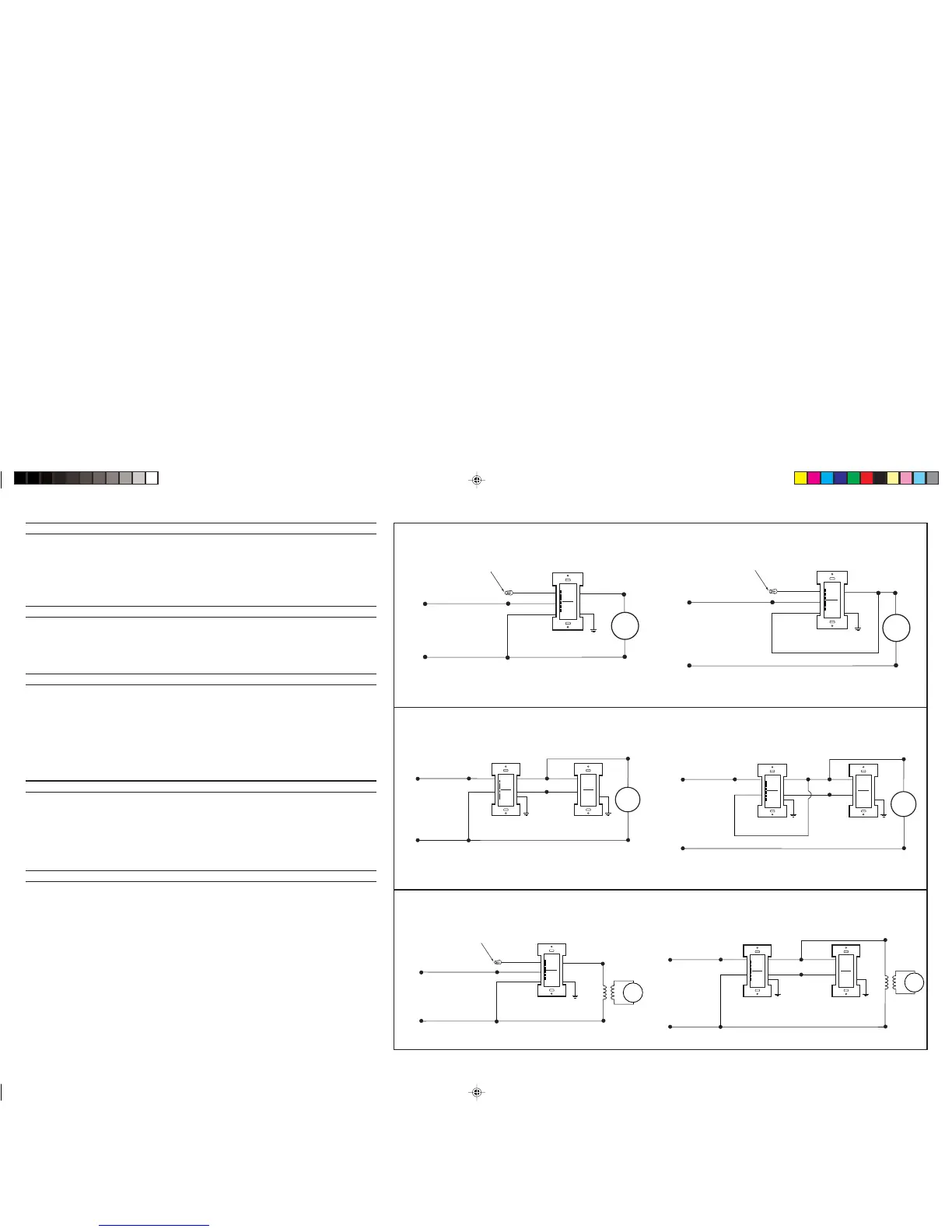
Wiring Diagram 3A – Single Magnetic Low-Voltage Application
PK-93052-10-00-0A
Load
Hot (Black)
Neutral (White)
Black
Yellow
Black
White
Blue
Green
Ground
Line
120VAC, 60Hz
Cap with
Wire Connector
White
Universal
Dimmer
Wiring Diagram 2 – 3-Way Application (Incandescent)
Load
Hot (Black)
Neutral (White)
Universal
Dimmer
Blue
Blue
Yellow
Yellow
Green
Ground
Green
Ground
Black
White
Line
120VAC, 60Hz
Multi-Remote
MS
ØØ
R-1
Black
White
Load
Hot (Black)
Neutral (White)
Universal
Dimmer
Blue
Blue
Yellow
Yellow
Green
Ground
Green
Ground
Black
White
Line
120VAC, 60Hz
Multi-Remote
MS
ØØ
R-1
Black
White
Application without Neutral Wiring
Application with Neutral Wiring (Preferred)
Wiring Diagram 1 – Single Pole Application (Incandescent)
Application without Neutral WiringApplication with Neutral Wiring (Preferred)
Hot (Black)
Neutral (White)
Black
Yellow
Black
White
Blue
Green
Ground
Line
120VAC, 60Hz
Cap with
Wire Connector
White
Universal
Dimmer
Load
Hot (Black)
Neutral (White)
Black
Yellow
Black
White
Blue
Green
Ground
Line
120VAC, 60Hz
Cap with
Wire Connector
White
Universal
Dimmer
Load
Hot (Black)
Neutral (White)
Universal
Dimmer
Blue
Blue
Yellow
Yellow
Green
Ground
Green
Ground
Black
White
Line
120VAC, 60Hz
Multi-Remote
MS
ØØ
R-1
Load
Black
White
Wiring Diagram 3B – 3-Way Magnetic Low-Voltage Application
PK-93052-10-00-0A 3/14/02, 12:06 PM2
 Loading...