3-Way or More Applications (Multi-Location)
Decora
®
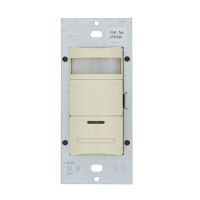
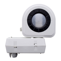
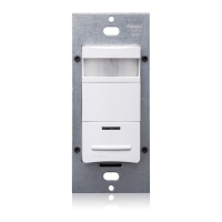
Manual-ON Occupancy Sensor Remote
California Title 24 2005 Compliant
Cat. No. IPP0R
120VAC, 60Hz
No Minimum Load Required
Compatible with incandescent lamps, electronic and magnetic low-voltage ballasts, electronic and magnetic ballasts, and fans.
INSTALLATION INSTRUCTIONS
DI-000-IPP0R-02A
WARNINGS AND CAUTIONS:
• To be installed and/or used in accordance with appropriate electrical codes and regulations.
• If you are unsure about any part of these instructions, consult a qualified electrician.
• Controlling a load in excess of the specified ratings will damage the unit and pose risk of fire, electric
shock, personal injury or death. Check your load ratings to determine suitability for your application.
• Do not install this unit to control a receptacle.
WARNINGS AND CAUTIONS:
• The Manual-On Occupancy Sensor Remote is intended to replace a standard light switch.
• Do not touch the surface of the lens. Clean outer surface with a damp cloth only.
• Disconnect power at circuit breaker or fuse when servicing, installing or removing fixture.
• Use this device only with copper or copper clad wire. With aluminum wire use only devices marked CO/ALR or CU/AL.
WIRING CONTROL (wall box with Load connection):
Connect wires per WIRING DIAGRAM as follows:
• Green or bare copper wire in wall box to Green terminal screw on control.
• Load wall box wire identified (tagged) when removing old switch to terminal screw
marked "RD" on control.
• First Traveler Line Hot to terminal screw marked "BK" on control.
• Remove Red insulating label from terminal screw marked "YL/RD" on control.
• Second Traveler wall box wire
(note color as above) to terminal screw marked
"YL/RD" on control. This traveler from the control must go to the terminal screw on
the sensor remote marked "YL/RD".
• Line neutral wall box wire to terminal screw marked "WH" on control.
IPP0R Remote
(3-Way Wall box from Step 2)
VZ0SR Remote
(4-Way Box from Step 2)
Control
(3-Way Wall Box from Step 2)
Terminal
Screw marked
White (WH)
Terminal
Screw marked
White (WH)
Terminal
Screw marked
Red (RD)
BK
W
H
YL/RD
RD
3
2
1
4
5
Terminal
Screw marked
Yellow/Red
(YL/RD)
Terminal
Screw marked
Black (BK)
Terminal
Screw marked
White (WH)
BK
W
H
YL/RD
RD
4
3
5
1
2
Terminal
Screw marked
Yellow/Red
(YL/RD)
Terminal
Screw marked
Black (BK)
Additional
Neutral Wire
Additional
Neutral Wire
BK
Y
L
/R
D
W
H
R
D
4
3
5
6
2
1
Terminal
Screw marked
Yellow/Red
(YL/RD)
Terminal
Screw marked
Black (BK)
Hot (Black)
Neutral (White)
Control
IPP0R Remote
VZ0SR Remote
YL/RD
YL/RD
RD
WHWH
BK
YL/RD
WH
BK
BK
Line
120VAC, 60Hz
Black
White
Green
Ground
Green
Ground
LOAD
Green
Ground
4-Way Wiring with Sensor Remote for Controls with Neutral
Connection Application:
NOTE: IPP15 sensor is depicted as control device.
NOTE: The control must be installed in a wall box that has a Load connection. The
sensor remote must be installed in a wall box with a Line Hot connection and a Neutral
connection. A Neutral wire to the sensor remote needs to be added as shown.
If you are unsure about any part of these instructions, consult a qualified electrician.
NOTE: Maximum wire length from control to all installed remotes cannot exceed
300 ft (90 m).
WIRING SENSOR REMOTE (4-Way wall box with Line Hot connection):
Connect wires per WIRING DIAGRAM as follows:
• Green or bare copper wire in wall box to Green terminal screw on sensor remote.
• First Traveler and Third Traveler wall box wire to remote terminal screw marked "BK"
in 4-way box, and to terminal screw marked "BK" of the remaining remote in 3-way
box.
• Second Traveler (tagged) and Fourth Traveler (tagged) wall box wire from control
in 3-way box to sensor remote terminal screw marked "YL/RD" in 4-way box and to
terminal screw marked "YL/RD" of the remaining remote in 3-way box (note wire
colors). This traveler from the remotes must go to the terminal screw marked
"YL/RD" on the control.
• Line Neutral wall box wire to remote terminal screw marked "WH".
WIRING SENSOR REMOTE (3-Way wall box with Line Hot connection):
Connect wires per WIRING DIAGRAM as follows:
• Green or bare copper wire in wall box to Green terminal screw.
• Line Hot (common) wall box wire identified (tagged) when removing old switch and
First Traveler wall box wire to control terminal screw marked "BK".
• Second Traveler wall box wire from control to remote terminal screw marked "YL/RD"
(note wire color as above). This traveler from the remote must go to the terminal
screw marked "YL/RD" on the control.
• Line Neutral wall box wire to remote terminal screw marked "WH".
Step 4a cont’d
Step 4b
WIRING CONTROL (3-Way wall box with Load connection):
Connect wires per WIRING DIAGRAM as follows:
• Green or bare copper wire in wall box to Green terminal screw on control.
• Load wall box wire identified (tagged) when removing old switch to terminal
screw marked "RD" on control.
• First Traveler Line Hot to terminal screw marked "BK" on control.
• Remove Red insulating label from terminal screw marked "YL/RD" on control.
• Second Traveler wall box wire
(note color as above) to terminal screw marked
"YL/RD" on control. This traveler from the control must go to the terminal screw
on the remote marked "YL/RD".
• Line Neutral wall box wire to terminal screw marked "WH" on control.
NOTE: The control must be installed in a wall box that has a Load connection.
The sensor remote must be installed in a wall box with a Line Hot connection and
a Neutral connection. A Neutral wire to the sensor remote needs to be added as
shown.
If you are unsure about any part of these instructions, consult a qualified
electrician.
NOTE: Maximum wire length from control to all installed remotes cannot
exceed 300 ft.
WIRING SENSOR REMOTE (wall box with Line Hot connection):
Connect wires per WIRING DIAGRAM as follows:
• Green or bare copper wire in wall box to Green terminal screw on sensor remote.
• Line Hot (common) wall box wire identified (tagged) when removing old switch
and First Traveler to terminal screw marked “BK” on control.
• Second Traveler wall box wire from control to sensor remote terminal screw
marked “YL/RD” (note wire color). This traveler from the remote must go to the
terminal screw on the control marked “YL/RD”.
• Line Neutral wall box to sensor remote terminal screw marked “WH”.
WIRING CONTROL (wall box with Load connection):
Connect wires per WIRING DIAGRAM as follows:
• Green or bare copper wire in wall box to Green terminal screw on control.
• Load wall box wire identified (tagged) when removing old switch to terminal
screw marked “RD” on control.
• First Traveler Line Hot to terminal screw marked “BK” on control.
• Remove Red insulating label from terminal screw marked “YL/RD” on control.
• Second Traveler wall box wire
(note color as above) to terminal screw marked
“YL/RD” on control. This traveler from the control must go to the terminal screw
on the sensor remote marked “YL/RD”.
BK
YL/R
D
R
D
4
3
2
1
5
Control
Terminal
Screw marked
White (WH)
BK
W
H
YL/RD
RD
4
3
5
1
2
IPP0R Remote
Terminal
Screw marked
Yellow/Red
(YL/RD)
Terminal
Screw marked
Black (BK)
Terminal
Screw marked
Yellow/Red
(YL/RD)
Terminal
Screw marked
Black (BK)
Additional
Neutral Wire
Terminal
Screw marked
Red (RD)
Hot (Black)
Neutral (White)
LOAD
Control
IPP0R Remote
YL/RD
YL/RD
RD
WH
BK
BK
Black
White
Line
120VAC, 60Hz
Green
Ground
Green
Ground
Step 4b cont’d
3-Way Wiring with Sensor Remote Application:
NOTE: IPP15 sensor is depicted as control device.
Step 4c
Side Wire Connection
Side wire terminals accept
#14 AWG solid copper wire only.
Back Wire (either hole may be used)
Back wire openings use #14-12 AWG
solid copper wire only.
• Make sure that the ends of the wires from the wall box are
straight (cut if necessary).
• Remove insulation from each wire in the wall box as shown.
Strip Gage (measure bare
wire here or use gage on
back of the sensor remote)
5/8”
(1.6 cm)
5/8”
(1.6 cm)
Step 3 cont’d
Strip Gage (measure bare
wire here or use gage on
back of the sensor remote)
Terminal
Screw marked
White (WH)
Terminal
Screw marked
White (WH)
Terminal
Screw marked
Red (RD)
BK
W
H
YL/RD
RD
BK
W
H
YL/RD
RD
4
3
5
1
2
3
2
1
4
5
ControlIPP0R Remote
Terminal
Screw marked
Yellow/Red
(YL/RD)
Terminal
Screw marked
Black (BK)
Terminal
Screw marked
Yellow/Red
(YL/RD)
Terminal
Screw marked
Black (BK)
Additional
Neutral Wire
Hot (Black)
Neutral (White)
ControlIPP0R Remote
YL/RD
RD
WH
BK
YL/RD
WH
BK
Black
White
Line
120VAC, 60Hz
Green
Ground
Green
Ground
LOAD
NOTE: The control must be installed in a wall box that has a Load connection. The
sensor remote must be installed in a wall box with a Line Hot connection and a Neutral
connection. A Neutral wire to the sensor remote needs to be added as shown.
If you are unsure about any part of these instructions, consult a qualified electrician.
NOTE: Maximum wire length from control to all installed remotes cannot exceed
300 ft (90 m).
WIRING SENSOR REMOTE (wall box with Line Hot connection):
Connect wires per WIRING DIAGRAM as follows:
• Green or bare copper wire in wall box to Green terminal screw on sensor remote.
• Line Hot (common) wall box wire identified (tagged) when removing old switch and
First Traveler to terminal screw marked "BK" on control.
• Second Traveler wall box wire from control to sensor remote terminal screw marked
"YL/RD" (note wire color). This traveler from the sensor remote must go to terminal
screw marked "YL/RD" on the control.
• Line Neutral wall box to sensor remote terminal screw marked "WH".
3-Way Wiring with Sensor Remote for Controls with Neutral
Connection Application:
NOTE: IPP15 sensor is depicted as control device.
Step 4a
Tools needed to install your Remote:
Slotted/Phillips Screwdriver Electrical Tape
Pliers Pencil
Cutters Ruler
INSTALLING YOUR REMOTE
NOTE: Use check boxes when Steps are completed.
Step 2
Step 1
Step 3
/./&&
/./&&
/./&&
/./&&
/./&&
/./&&
/./&&/./&&
/./&&
/./&&
/./&&
/./&&
4-Way
1. First Traveler – note color
2.
Second Traveler – tagged
3.
Neutral
4.
Ground
5.
Third Traveler – note color
6.
Fourth Traveler – tagged
NOTE: For matching remote
w/LEDs installation, the First
Traveler becomes Line Hot.
3-Way
1. Line or Load (See important
instruction below)
2.
Neutral
3.
Ground
4.
First Traveler – note color
5.
Second Traveler – note color
NOTE: For matching remote
w/LEDs installation, the First
Traveler becomes Line Hot.
Preparing and connecting wires:
This remote can be wired using side wire terminal screws or through
backwire openings. Choose appropriate wire stripping specifications
accordingly.
WARNING: TO AVOID FIRE, SHOCK, OR DEATH; TURN OFF
POWER at circuit breaker or fuse and test that power is off before wiring!
Identifying your wiring application (most common):
NOTE: If the wiring in the wall box does not resemble any of these
configurations, consult a qualified electrician.
IMPORTANT:
For 3-Way applications, note that one of the screw terminals from the old switch
being removed will usually be a different color (Black) or labeled Common. Tag that
wire with electrical tape and identify as the common (Line or Load) in both the sensor
wall box and remote wall box.
For 4-Way applications, note that the old switch being removed will have 4 screws
plus a ground screw. Tag the two same color insulated wires with electrical tape.