WARNINGS AND CAUTIONS:
To be installed and/or used in accordance with electrical codes and regulations.
• Ifyouareunsureaboutanypartoftheseinstructions,consultanelectrician.
• UseONLYwiththeappropriateAdvanceTransformer120VMark10™Powerline or Lutron Tu-Wire
®
electronicballastsforcontrollingthespecicuorescentlampsinFluorescentMode.
• Toavoidoverheatingandpossibledamagetothisdeviceandotherequipment,donotinstalltocontrolareceptacle,amotor-oratransformeroperatedappliance.
• Usewithmagneticlowvoltagetransformers,incandescent,or120Vhalogenxturesonly.UseaLevitonelectroniclowvoltagedimmertocontrolelectronic(solidstate)lowvoltagetransformers.
• WhenretrottingMark10™PowerlinedimmingballastsintoxturesthatoriginallyhadInstantStartballasts,thesocketsMUSTbereplacedwithRapidStartsocketstoallowproper
dimmeroperationandpreventdamagetothedimmerballast.Refertotheinstructionsprovidedwiththeballast.
• ViziaRF+
TM
dimmersarenotcompatiblewithstandard3-wayor4-wayswitches.TheymustbeusedwithcompatibleVizia+
TM
or
ViziaRF+
TM
controllersformulti-locationdimming.
WARNINGS AND CAUTIONS:
• Whenmagneticlowvoltagecircuitsareoperatedatadimlevel,withalllampsinoperative,excesscurrentmayowthroughthetransformer.Toavoidpossibletransformerfailuredueto
overcurrent,useatransformerthatincorporatesthermalprotectionorafuseattheprimarywindings.
• Fluorescentlampsmustbeburnedinatfullintensityfor100hourspriortodimmingforproperdimmingperformance.Useonlyone(1)ViziaRF+™Incandescent/MagneticLowVoltage
orFluorescentDimmerinamulti-locationcircuitwithupto9coordinatingremotes(withoutLEDs)orupto4matchingremotes(withLEDs).Theremote(s)willturntheloadon(“atthe
levelselected”fordimmersonly)atthecontrol.
• Totalminimumloadmustexceed40W.
• Dimmermayfeelwarmtothetouchduringnormaloperation.
• Recommendedminimumwallboxdepthis2-1/2".
• Maximumwirelengthfromdimmertoallinstalledremotescannotexceed300ft.
• Usethisdevice.
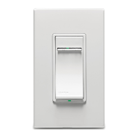
SinglePole(Onelocation)or3-Way(Multi-location)
Cat.No.VRMX1-1L,1000VA,1000W(Lighted)
120VAC,60Hz
INSTALLATION INSTRUCTIONS
For3-Wayapplications,notethatoneofthescrewterminals
fromtheoldswitchbeingremovedwillusuallybeadifferentcolor(Black)
orlabeledCommon.Tagthatwirewithelectricaltapeandidentifyasthe
common(LineorLoad)inboththedimmerwallboxandremotewallbox.
1-#12w/1to3#14,#16or#18
2-#12w/1or2#16or#18
1-#14w/1to4#16or#18
2-#14w/1to3#16or#18
DI-000-VRMX1-02A
• Pulloffpre-cutinsulationfromdimmerleads.
• Makesurethattheendsofthewiresfromthewallboxare
.
• Removeinsulationfromeachwireinthewallboxasshown.
Coordinating Remote (no LEDs)
YL/RD
Yellow/
Red
RD
White
Red
Black
Black
BKWH
White
Line
120VAC, 60Hz
(unused)
(unused)
Green
Ground
Green
Ground
Slotted/PhillipsScrewdriver ElectricalTape Pliers
Pencil Cutters Ruler
Inmulti-dimmerinstallations,thereductionofthedimmer’scapacityis
required.Refertothechartformaximumloadperdimmer.
IfinstallingDimmerinasingledeviceapplication,proceedwiththe
section.IfinstallingDimmerina
multi-deviceapplication,proceedasfollows:
Yourdevicemayincludecoloroptions.Tochangecoloroftheface
proceedasfollows:
UsecheckboxeswhenStepsarecompleted.
ONOFF
ONOFF
ONOFF
ONOFF
ONOFF
ONOFF
ONOFFONOFF
ONOFF
ONOFF
ONOFF
ONOFF
atcircuitbreakerorfuseandtestthatpower
isoffbeforewiring!
Step 1
Step 2
Ifthewiringinyourwallboxdoesnotresembleany
ofthesecongurations,consultanelectrician.
2
4
3
1
Line(Hot)
Neutral
Ground
Load
Line or Load
Neutral
Ground
FirstTraveler–notecolor
SecondTraveler–notecolor
2
4
1
5
3
5/8"
Pulloffpre-cutinsulationfromdimmerleads.Makesurethat
theendsofthewiresfromthewallboxare
.Removeinsulationfromeachwireinthewallbox
as shown:
(PRIMARY SIDE
OF BALLAST)
Red
Yellow/Red
White
White
Green
Ground
Insulating label:
This wire is used in 3-way installations only.
For single pole installations, do not remove this insulating label.
Y
ellow/Red
1
4
2
Black
White
Green
Red
3
Low-voltagedimmersareratedinVolt-Amps(VA).Themaximumbulbwattage
isdeterminedbytheefciencyofthetransformerinthelow-voltagelighting
system.Transformerefciencieswillvaryfromdifferentmanufacturers;
consider80%efcientasaverage.Usethecharttodeterminemaximumbulb
wattagefortypicaltransformerefciencyratings.
Mark10™PowerlinedimmersareratedinVolt-Amps(VA).Themaximum
bulbwattageisdeterminedbytheefciencyoftheMark10™Powerline
ballast.Thefollowingtableshowsthemaximumnumberofballaststhatcan
beconnectedtoasingledimmerfordifferentMark10™Powerline ballasts.
Alsonotethatthetableshowsmaximumballastsformulti-ganginstallations.
Todeterminetotalballastload,addthelinecurrentfoundontheballastlabel
forallballastsinthecircuit.Thiswillindicatethetotalloadforthecontrol.
sections
Do not
sections
side section
650W
650VA
800W
800VA
Single
1000W
1000VA
Load
Incand
MagLV
520W
Rating
1000VA
Single
800W
Two Gang
640W
INTRODUCTION
Leviton’sViziaRF+
TM
componentsaredesignedtocommunicatewith
eachotherviaRadioFrequency(RF)toprovideremotecontrolofyour
lighting.UsingRFtechnologyallowsLevitontoprovidethegreatest
signalintegritypossible.EachmoduleinLeviton’s
ViziaRF+
TM
componentlineisaZ-Wave
®
enableddevice.Ina
Z-Wave
®
network,eachdeviceisdesignedtoactasarouter.These
routerswillre-transmittheRFsignalfromonedevicetoanotheruntil
theintendeddeviceisreached.Thisensuresthatthesignalisreceived
byitsintendeddevicebyroutingthesignalaroundobstaclesandradio
deadspots.TheSceneCapableIncandescent/MagneticLowVoltage
orFluorescentDimmeriscompatiblewithanyZ-Wave
®
enabled
network,regardlessofthemanufacturerandcanalsobeusedwith
otherdevicesdisplayingtheZ-Wave
®
logo.
RemembertoexercisegoodcommonsensewhenusingtheTimer
featuresofyourremote,especiallywhenschedulingunattended
devices.Therecanbesomeunexpectedconsequencesifnotused
withcare.Forexample,anemptycoffeepotcanberemotelyturned
on.Ifthatshouldhappen,yourcoffeepotcouldbedamagedfrom
overheating.Ifanelectricheateristurnedonbyremotecontrolwhile
clothingisdrapedoverit,arecouldresult.theremote
forthecontrolofhighpowerheatingappliancessuchasportable
heaters.Thisdevicewillnotcontrollightingthatisusedwithelectronic
low-voltageandhighfrequencypowersupplytransformers,norhigh
pressuredischargelamps(HIDlighting).Thisincludesmercury-vapor,
sodiumvaporandmetalhalidelamps.
• SoftfadeON/OFF
• Scenecapable
• ON/OFFLEDandBrightnesslevelLED
• Twowaycommunication
• RFreliability
• Easeofinstallation–Nonewwiring
• CompatiblewithotherZ-Wave
®
enableddevices
FORMAGNETICLOW-VOLTAGEAPPLICATIONS,
CONNECTDIMMERONLYTOTHEPRIMARY(HIGH-VOLTAGE)
SIDEOFAMAGNETICLOW-VOLTAGETRANSFORMER.
WhenusingthecoordinatingremotewithoutLEDs,thedimmer
canbeinstalledoneithertheLineorLoadsideofthe3-waycircuit.
Maximumwirelengthfromdimmertoallinstalledremotescannot
exceed300ft(90m).
• GreenorbarecopperwireinwallboxtoGreendimmerlead.
• LineHot(common)wallboxwireidentied(tagged)whenremoving
oldswitchtoBlackdimmerlead.
• FirstTravelerwallboxwiretoReddimmerlead.
• RemoveRedinsulatinglabelfromYellow/Reddimmerlead.
• SecondTravelerwallboxwiretoYellow/Reddimmerlead
.Thistravelerfromthedimmermustgotothe
terminalscrewontheremotemarked"YL/RD".
• LineNeutralwallboxwiretoWhitedimmerlead.
"BK"and"RD"terminalsoncoordinatingremoteareunused.
Tighten both screws.
Maximumwirelengthfromdimmertolastremoteis300ft(90m).
• GreenorbarecopperwireinwallboxtoGreenterminalscrew.
• Loadwallboxwireidentied(tagged)whenremovingoldswitchtoFirst
Traveler.
• SecondTravelerwallboxwiretoterminalscrew
marked"YL/RD".Thistravelerfromtheremotemustgotothe
Yellow/Reddimmerlead.
• RemoveWhiteinsulatinglabelfromterminalscrewmarked"WH".
• LineNeutralwallboxwiretoterminalscrewmarked"WH".
•
CONNECTAMAGNETICLOW-VOLTAGEDIMMERONLY
TOTHEPRIMARY(HIGH-VOLTAGE)SIDEOFAMAGNETIC
LOW-VOLTAGETRANSFORMER.
• GreenorbarecopperwireinwallboxtoGreendimmerlead.
• LineHotwallboxwiretoBlackdimmerlead.
• LoadwallboxwiretoReddimmerlead.
• LineNeutralwallboxwiretoWhitedimmerlead.
• Yellow/ReddimmerleadshouldhaveRedinsulationlabelafxed.
IfinsulatinglabelisnotafxedtoYellow/Reddimmerlead,
useelectricaltapetocover.
• .
TM
Powerline
TM
Powerline
Single
Gang
Two
Ganged
2 Gang
REZ-2Q18-M2-LD
REZ-1T32
REZ-2Q26
REZ-1T32
REZ-1T42
REZ-1Q18-M2-BS
REZ-1Q18-M2-LD
REZ-2Q18-M2-BS
REZ-1T32
REZ-1T42-M2-BS
REZ-1T42-M2-LD
REZ-2Q26
REZ-2Q26-M2-BS
REZ-2Q26-M2-LD
REZ-1Q18-M2-BS
REZ-1Q18-M2-LD
REZ-2Q18-M2-BS
REZ-2Q18-M2-LD
REZ-1T42-M2-BS
REZ-1T42-M2-LD
REZ-2Q26-M2-BS
REZ-2Q26-M2-LD
REZ-1T42-M2-BS
REZ-1T42-M2-LD
REZ-2T42-M3-BS CFTR32W/GX24Q 13 10 8
CFTR32W/GX24Q 26 20 16
CFTR32W/GX24Q 26 20 16
CFTR26W/GX24Q 17 13 11
CFTR26W/GX24Q 17 13 11
CFTR26W/GX24Q 32 25 20
CFTR26W/GX24Q 32 25 20
CFTR18W/GX24Q 23 18 15
CFTR18W/GX24Q 23 18 15
CFTR18W/GX24Q 46 37 30
CFTR18W/GX24Q 46 37 30
CFQ26W/G24Q 17 13 11
CFQ26W/G24Q 17 13 11
CFQ26W/G24Q 17 13 11
CFQ26W/G24Q 32 25 20
CFQ26W/G24Q 32 25 20
CFQ26W/G24Q 32 25 20
CFQ18W/G24Q 23 18 15
CFQ18W/G24Q 46 37 30
CFQ18W/G24Q 46 37 30
CFM42W/GX24Q 20 16 13
CFM32W/GX24Q 26 20 16
CFM26W/GX24Q 17 13 11
CFM26W/GX24Q 32 25 20
151823CFM18W/GX24Q