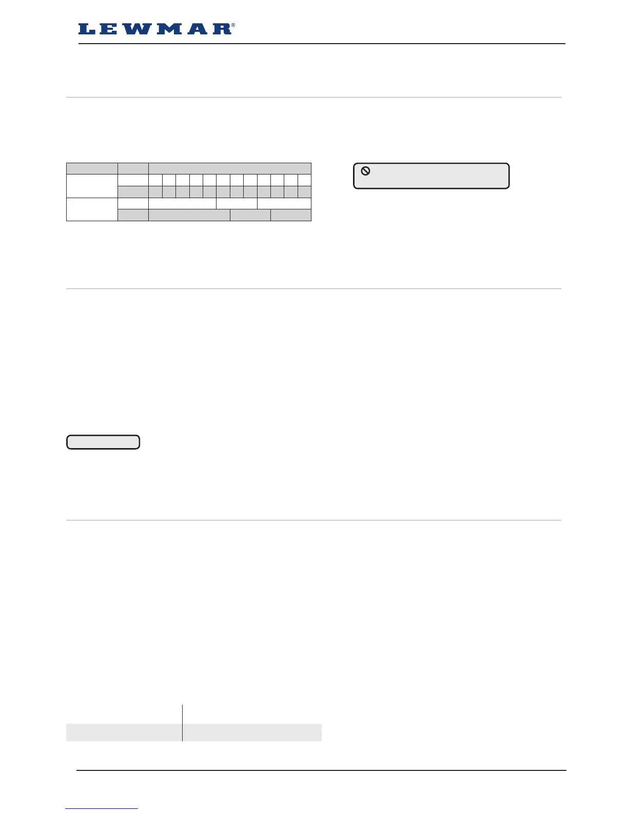
CABLE SELECTION
Cable length
up to
Feet 7 13 20 26 33 40 46 53 60 66 73 80
Metres 2 4 6 8 10 12 14 16 18 20 22 24
Cable Size
AWG 8 6 4
mm
²
10 16 25
WIRELESS REMOTE
3 BUTTON WINDLASS ONLY
WIRELESS REMOTE
5 BUTTON WINDLASS & THRUSTER
68000967 68000968
S900/S2000 windlass ref B10500 iss.1 | 9
5- Electrical wiring
5.1 Electric cable selection
Lewmar recommends the installer source and install cable that meets the requirements of the standards and
regulations relevant to the installation and codes of practice.
The cable table gives recommended cable sizes based on total length of cable required, from the battery, follow-
ing the route of the cables.
5.2 Wiring
Plan the installation to suit the controls and give the operator a full view of the windlass. The wiring system
should be of the fully insulated type, which avoids possible electrolytic corrosion problems. We recommend the
use of type III stranded, tinned copper wire with copper crimp terminals. Most modern installations are negative
return (negative ground) but polarity should be checked.
Overload protection, in the form of the circuit breaker provided must be built into the windlass wiring circuit.
• Circuit breaker supplied:
S900 - 90A (Part No 68000349)
S2000 - 110A (Part No 68000350)
• The circuit breaker should be positioned close to the battery in a dry, readily accessible place.
• The breaker must be manually reset should an overload occur that causes it to trip to the off position.
• If you are not sure you understand these guidelines, seek professional help. Ensure that the installation
complies with USCG, ABYC, NMMA or other local regulations.
WARNING!
5.3 Control switch installation
The unit is supplied with
• Guarded rocker switch (product ref 68000593)
• Contactor Assy
- S900 - 68001213
- S2000 - 68001214
• Follow wiring diagram 5.4
NOTE: Optional electric footswitches and remote handheld control available.
Visit www.lewmar.com for more information
Optional wireless remote also available
See table below for models and references
Windlass performance is directly related to cable size and length.
Voltage drop over the complete wiring run must not exceed 10%.
NOTE: In a multi station installation all switches must be wired in a parallel circuit.
DO NOT confuse cable length
with the length of the vessel
 Loading...