3
300 mm
(12”)
25-30 mm
1” - 1 ³/₁₆”
4
2
1
S900/S2000 windlass ref B10500 iss.1 | 5
4- Installation
4.2 Accessories
Use only genuine Lewmar parts and accessories to ensure top performance and eliminate the risk of voiding your
warranty. For replacement parts, please visit your dealer or www.lewmar.com
4.3 Bulkhead preparation
IMPORTANT - Plan location carefully at the stern of the vessel and allow for the following:
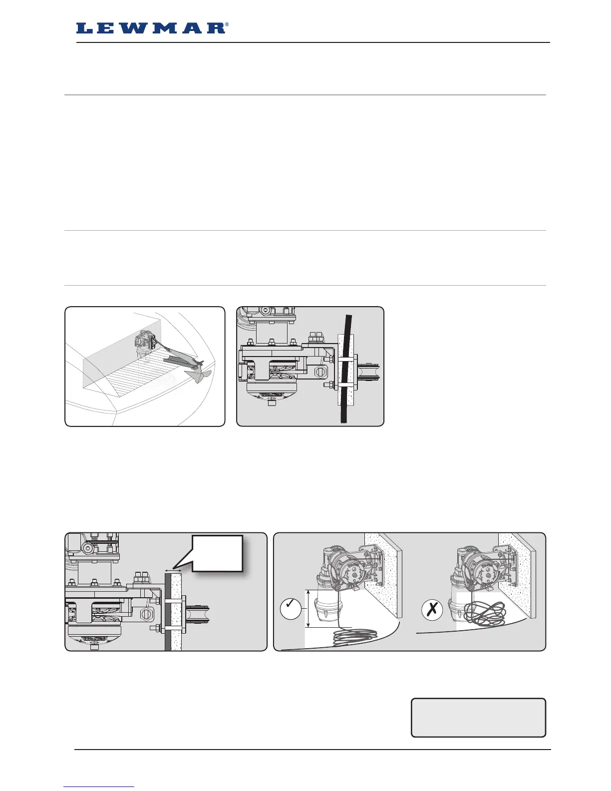
1. Select an appropriate position taking into consideration the position of the anchor roller and the locker behind
the bulkhead . Lead from the roller should be fed in-line back to the the pulley and along its centre line.
2. If the bulkhead is not flat, a suitable mounting pad may be required to take up camber or sheer.
NOTE: If in doubt about the suitable construction of the pad consult a qualified marine engineer.
The bulkhead is an integral component of the windlass. It has to secure the windlass and be strong enough
to cope with the high torque stresses involved in recovering the anchor. Thin bulkhead made of foam or balsa
laminate construction, will require reinforcement in order to spread the loads applied while the windlass is in
use.
1. Lewmar recommends a minimum bulkhead thickness of 25mm (1”),
M8 Screws supplied suit bulkhead and packing thickness of 25-30mm (1” - 1 ³/₁₆” ).
Note: For thicker bulkheads, please source suitable length M8 countersunk screws.
2. Check clearance behind the bulkhead to fit the windlass including the motor
gearbox and allow for sufficient vertical fall (minimum of 300 mm /12” at all
times) for the lead line when hauling in.
WINDLASS INSTALLATION
• An appropriate marine sealant
• Electric drill and 9mm (⅜”) drill bit
• 50mm (2”) Hole Saw
• 5mm (³/₁₆”) Allen Key
• 13mm (½”) Spanner
WIRING INSTALLATION
• Crimping Pliers / Wire Stripper
• Suitable electrical cable and crimp terminals
4.1 Basic requirements
Each installation requires the following tools:
WARNING! Failure to
provide minimum vertical
fall will cause jamming.