1
3
2
S900/S2000 windlass ref B10500 iss.1 | 15
7- Servicing
7.1 Servicing schedule
The service period is determined by the frequency of use. Professional user will need to carry out these operations
more oen than the weekend user. Before commencing any work on this or any other electrical product, isolate
from the power source.
Bedding in period:
When new there are some areas that will need frequent checking. If no movement is found they can be inspected
less oen.
• Examine all electrical connections, to make sure they are sound and corrosion hasn’t set in.
Tighten if necessary and protect if required.
• Check mounting scews are firmly clamped and tighten if required.
Aer use:
• Wash down the windlass using fresh water.
• Ensure rode is at least 12” (300mm) below the windlass
• Check anchor locker drain
• Check rode for wear.
Annually or more oen if frequent user:
• Examine all electrical connections, to make sure they are sound and corrosion hasn’t set in.
Tighten if necessary and protect if required.
• Check mounting screws are firmly clamped and tighten if required.
• Check rode for wear.
• Check gypsy as it is a high wear item (For service and replacement see §7.2)
WARNING! Isolate the windlass
using circuit breaker/isolator
WARNING! Ensure rode is adequately
secured to an independent strong point
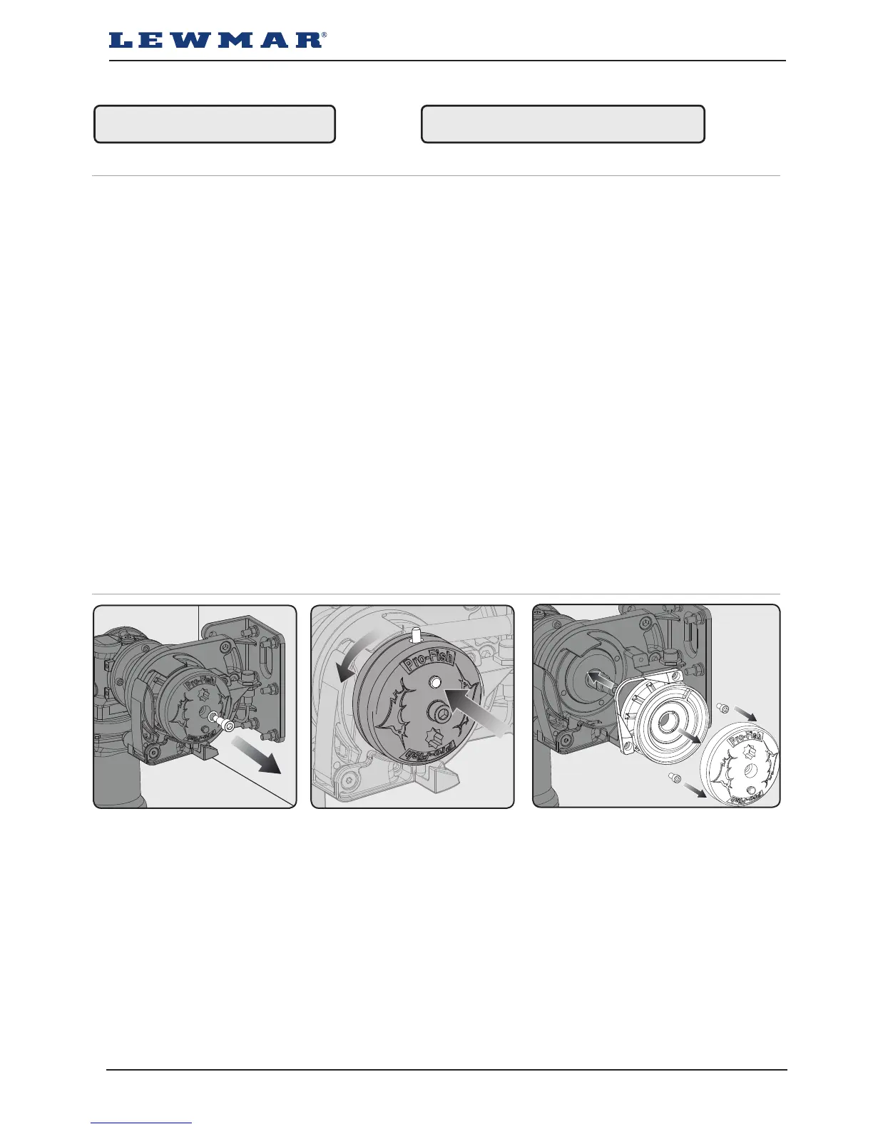
7.2 Gypsy replacement/service
1. Remove screw and washer from drive cap. Screw may require warming as it is sealed with Loctite
®
2. Depress plunger so that it is held inside drive cap and unscrew pro-fish mechanism.
3. Remove stripper retaining screws
• Pull control arm away from the gypsy.
• Move stripper to clear housing and remove the gypsy, take care to note direction of rope teeth for reassembly.
• Check parts for wear and replace as appropriate
• Clean thoroughly without solvent or wire brush and dry.
• Clean and lubricate Pro-Fish plunger.
• Re-Assemble, use a small amount of grease on the mating faces.
• Use loctite® on the assembly screws, making sure no Loctite residue gets on the thread of the driveshaft as it
will prevent the free fall function operating. The screws (Fig 3), Retaining the stripper should be tightened, then
backed off ½ torn to allow the stripper to lay loose on the gypsy.
 Loading...